This text is written by DMO, COPYRIGHT DMO
Introduction to Scattering Theory
Application to Telescope Mirrors
Using IRIS 908RS
Table of content
Part One: pdf file
1. What causes optical scattering in a telescope?
2. How do we measure the scattering properties of a surface?
3. What is the usual way of expressing the scattering of an optical surface ?
Part Two: pdf file
4. What can we learn from surface scattering theory?
First level understanding
The exact vectorial theory
The empirical Harvey relation
Part Three: pdf file
5. Application of the Harvey law to telescope mirrors
Example
Limitations of the Harvey law
HTML version below:
1. What causes optical scattering in a telescope?
A perfect optical surface deflects an optical beam specularly, i.e. in straight lines following Snell's laws. A parallel beam of diameter D should ideally be focused at one point by a perfect telescope mirror.
Because of diffraction phenomenon at the entrance of the telescope, the power of the inlet beam is spread onto a small area instead of a single point. The diffracted angular deflection with respect to purely specular directions are very small; they depend on the beam diameter D (it is the telescope diameter) and the wavelength lambda so most of the power falls inside a solid angle circle of an angular radius 1.22*lambda/D. This is known as the Airy disk for a circular opening. Since this is the minimum image dimension for perfect conditions, it is used as a natural scale in our discussion.
If the surface is not perfect and the defects are smaller than a few wavelengths (and smaller than the coherence length of the source), some additional power will fall outside the Airy disk. This type of scattering yields to mathematical analysis, allowing to compute the relation between the physical shape of the defects (micro-roughness) and the resulting optical scattering. This is typically the case of a good optical surface such as a clean optical mirror.
If the defects are very large compared to the wavelength, power is scattered at large angles with respect to the specular direction. There is no theory for accounting for this type of scattering, but only empirical relations (between physical defects size and distribution, and scattering). One can visualize the surface as covered by thousands of microscopic mirrors of all shapes and various dimensions placed at all angles with the mean surface. There cannot be a theory because there are as many scattering functions as there are distributions of micro-mirrors. This is the case of dusty optical mirrors or of ground glass. Hence, it is improper to convert the scattering measurements of a dusty mirror into micro-roughness values.
2. How do we measure the scattering properties of a surface?
The scattering properties of a surface is measured by a scatterometer. This instrument essentially throws a well collimated beam on the test surface at a well defined incidence angle, and one or several detectors detect and measure the scattered light. These detectors are mounted on arms so that the scattering angle can be varied. The scattering solid angle is defined by baffles and stops.
Usually it is very difficult and inaccurate to measure directly the scattering at angles smaller than 2 or 3°. This is due to straylight within the instrument. The latter is mainly produced by dust and stains on the front collimating lens and, hence is essentially variable. If it is not too important, and if we measure the transmission scattering, the instrument stray light can be approximately removed by calibration, measuring without sample. This calibration procedure, of course does not work for reflective measurements since then, no measurement is possible without sample. Also, portable instruments are bound to utilize short path beams with relatively large apertures; hence, baffling for small angles is impossible.
In reflective measurements of mirrors before aluminizing, the measurement is usually polluted by a certain amount of volume scattering by the bulk of the blank. This difficulty disappears of course when the mirror is aluminized.
3. What is the usual way of expressing the scattering of an optical surface ?
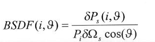
There are basically two related ways. First the angle-resolved scattering known as Bi-directional Scattering Distribution Function (BSDF). This function is the relation between the light power received within a solid angle in a certain scattering direction depending on the beam incidence angle and its power. The second is the Total Integrated Scattering (TIS). It is a global scattering function that says how much of the incident power is scattered in all direction depending on the incidence to the surface. The TIS function cannot be used to quantify the effect of scattering on the image sharpness in a telescope.
The BSDF is mostly utilized in its simplified form where only the incidence plane is considered :
In this expression, i is the incidence angle of the source beam (from the normal to the scattering surface), theta is the scattering direction (from the normal), Pi is the power in the incident beam, dPs is the power in the scattered beam inside the solid angle dOmegas around the direction theta . It is assumed that the whole illuminated surface is seen by the scattering detector or that the powers are expressed per unit area of the scatterer. The BSDF is expressed in steradians-1. These measurements are well known and documented in optics [Jean M. Bennet and Lars Mattsson, Surface roughness and scattering, OSA, Washington D.C.] [John C. Stover, Optical Scattering, SPIE Opt. Eng. Press].
Let us consider an example. The incident beam on a surface is 100 mW. Its angle from the normal direction is 45°. There is a sensor located at 50 mm from the surface at an angle of 20° from the normal. The sensor is circular and its diameter is 4 mm. How much power will reach the sensor if the BSDF(45°,-20°) of the surface is 0.003% of steradians-1 ?
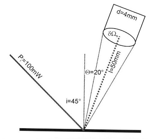
The surface of the sensor is Pid2/4. The solid angle (dOmegas) of the sensor related to the incident spot on the surface is 4Pi(surface of the sensor)/(surface of the sphere) = Pid2/4l2 = 0.005027 steradians. From the BSDF definition, the power collected by the sensor is dPs(45°,20°) = BSDF(45°,20°) x Pi x dOmegas x cos(20°) = 0.00003 x 100 x 0.005027 x 0.939692 = 0,0000142 mW. This example shows that if the BSDF is known, it is possible to calculate how much light is going in any direction for a given incident beam power. The IRIS 908RS from DMO calculates the BSDF. Later on, it will be shown how to apply this for telescope mirrors.
The BSDF is a monotonous decreasing function which covers several orders of magnitudes when going from small angles with respect to the specular direction (the direction where the beams proceeds when there is no scattering) to large angles. When the scattering is measured on the side of the transmitted beam, one calls the function the BTDF, and when measured on the side of the reflected beam, it is called the BRDF (so that the BSDF of a transparent surface is the junction of its BTDF and its BRDF).
Relation between BSDF and radiance
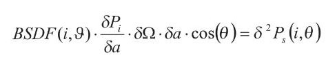
One can rearrange the BSDF definition equation to show its relation to the radiometric quantity "radiance" by replacing the total incoming power by the power per surface unit da:
one see that the radiance is : 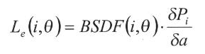
4. What can we learn from surface scattering theory?
We invoque rapidly some theoretical concepts about surface scattering to make the choices and recommendations understandable by non specialists. Thus, there is no attempt at being exhaustive or even strictly consistent. One should also remember that it applies only to limited cases : pure surface scatterers with defects not much larger than the wavelength.
One can think of a surface scatterer in terms of a superposition of many ruled gratings of various pitch and ruling directions. The first theoretical analysis of scattered light was simply made in term of Fourier analysis of the frequency and amplitude content of the scattering surface. From these early (but conceptually very easy to understand) studies, one should remember the two basic relations :
The grating equation relating the ruling pitch d, the wavelength lambda of the light and the incidence (i) and diffraction (theta) directions :
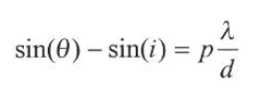
p is the integer diffraction order. The relation giving the diffracted intensity for small angles between specular and scattering directions (i~theta) and for a depth a of the grooves is :
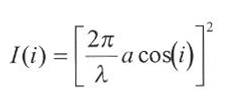
Of course, one cannot go very far with this treatment. But on top of being very easy to grasp, it already shows characteristic features which will stay with us in the most advanced theories of surface scattering.
Considerable amount of work has been devoted to surface scattering. Finally, the most exact treatment is known as the Rayleigh-Rice perturbation theory.
This yields the following result :
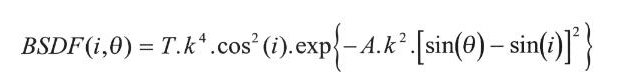
where T is the transmission of the sample and k = 2Pi/lambda. This equation is somewhat simplified :
It is remarquable that we find again the two features we had pointed out from the grating theory. A third useful features is comprised in the Rayleigh-Rice relation : the fourth power dependence on wavelength. It can be used to compute the BSDF at a wavelength from the measurements made at another wavelength.
As we already pointed out, this is in fact all we need in order to build the most economic and reliable instrument. The Harvey model of surface scatterer follows the law :
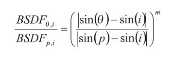
Where p is a conventional "pivot" angle, usually very small, and m (usually negative) is the slope of the log-log diagram of the BSDF as a function of the angular variable |sin(theta)-sin(i)| or |betas-betai| . The Harvey relation is mostly utilized in this logarithmic form because its structure is very simple (a straight line of slope m):
Y = Y0 + m*X
where Y = log(BSDF), X = log(|betas-betai|) and Y0 comprises the constant terms.
One notice that if two BSDF measurements are performed on a sample at two different angles, the Harvey relation allows to compute b = BSDFp,i and the slope m. The choice of p is arbitrary and can be chosen as a significant angle for the particular application one has in mind. For IRIS 908RS, the incidence angle is i = 45°.DMO has chosen p = 45°- epsilon0, epsilon0 = 1.75°, and the instrument will compute b and m from the measurements at theta = 0° (45° from the specular direction) and at theta = 30° (15° from the specular direction). These data then allow to compute the BSDF at any angle.
The Harvey relation turns out to be an excellent representation of the scattering behavior of well behaved surface scatterers such as clean polished mirrors with small defects. If the scatterer is not well behaved (as a dusty mirror for instance), the Harvey law still represents good portions of the angular dependency of the BSDF, but is less accurate for angles outside the range of the two calibration angles.
5. Application of the Harvey law to telescope mirrors
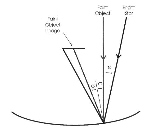
A typical astronomy application would be the following. Assume that you measure a faint stellar-like object close to a bright star with a pixel detector (see picture here above). Because the mirror is not perfect nor clean, a part of the light from the bright star will be scattered in the direction of the faint object image. It is a parasitic source of light. Thanks to the BRDF function of the mirror, it is possible to estimate what is the magnitude of the bright star scattered light and compare it to the magnitude of the faint objet.
Let say that the pixel size covers a field of view of a solid angle alpha x alpha (alpha is an angle in radians. To convert second of arc to radians use the following formula : radians = second of arc x Pi / 648000). The distance between the bright star and the faint object is e. From the measurement performed with the IRIS 908RS, the Harvey coefficients b and m are known.
On the picture here above, we consider what is happening at a certain location on the mirror. At that location, the slope of the mirror is sigma. We will see that this slope is without importance in the calculation. What we want to know is how much light coming from the bright star is scattered in the faint object image direction. So the incident angle of the bright star is sigma + epsilon. The scattered light angle is sigma. Now we can calculate the BRDF function for those incident and scattering angles :
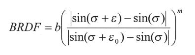
where epsilon0 is the pivot angle of the Harvey law (epsilon0 = 1,75° for IRIS 908RS). Because all angles are very small, the sinus of the angles are the angles themselves. The BRDF formula can be simplified :
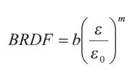
As previously mentioned, the slope of the mirror has disappeared from the formula. The only important factor is the distance between the faint object and the bright star (epsilon). Because the BRDF is defines as follow :
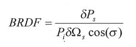
it is possible to calculate how much of the bright star light is polluting the faint object viewing. In this formula, cos(sigma) is nearly 1 as the angle sigma is very small. dOmegas is the solid angle of scattered light per pixel. In our case it is the pixel size alpha x alpha. Pi is the power of the bright star. Combining BRDF definition and Harvey law, one sees that :
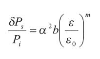
The same formula expressed in magnitude is :
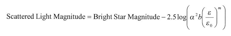
The pixel size is 0.5" x 0.5". The bright object is of magnitude 2; what amount of (parasitic) light from the bright object is polluting your faint object if the distance between the two object is 5" and the IRIS scattering measurement on the primary yields the values m = -2.168 and b = 0.3618 ?
In the formula here above, alpha = 0.5 x Pi / 648000 = 2.42 10-6 radian and epsilon = 5 / 3600 = 1.39 10-3 °. epsilon0 is a constant value (1,75° for IRIS 908RS). Therefore
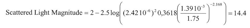
The light scattered by the bright star has a magnitude of 14.4 per pixel.
The main drawback of the Harvey representation is that it breaks down at very small angles since its mathematical formulation exhibits a singularity at theta = i. This makes the result of the preceding section approximate, since the BRDF at 5" from the specular direction has been deduced from measurements made at 15° and 45° from the specular direction. The result should not be used in correcting the photometry of the faint object, but just to make a preliminary estimate of what can be expected. For instance, such computation will show immediately whether the mirror cleanliness is critical for a given observation. The actual photometric calibration of the scattering should be performed by measuring an empty field at the same distance of the bright star.