The most up to date data on the performance of the spectrograph: Changes in and additions to cameras, CCDs, gratings, etc... are available here [1]. Visitors and prospective users should be sure and read this information carefully.
Instrument Control Software [2]
Virtual Smart Motor Controller [3] (ARCON-IRAF)
ICS Info [4] (ARCON-IRAF)
Basic optical characteristics [5] of the spectrograph formerly part of the CTIO Facilities Manual. This information is obsolescent and is often superceded by newer data in the "Recent Developments" section above.
Tim Abbott (tabbottATnoao.edu)
| Contents | |
| 1. | Introduction |
| 2. | Setup |
| 3. | Operation |
| 4. | RC Spectrograph description |
| 5. | Setup motor |
| 6. | Directory tree |
LabView based Motion Control
User Manual
The update of the RC Spectrograph is based on the step motors and encoders subtitution by SilverMax (TM) intelligent motors, from QuickSilver Controls Inc.
The SilverMax (TM) is a fully integrated motion control system with a motion trajectory controller, a motor driver electronics, a position encoder and a motor, all contained in one unit.
SilverMax (TM) connects to a standard PC RS-485 interface.
The SilverMax (TM) motor brings a commands set that permit move motors, controlling different movement profiles: position, speed and time.
See main SilverMax (TM) motor characteristics in Apendix A.
The following mechanisms were updated:
| Mechanism positions |
| Slit 0 to 50.000 microns |
| Comparison Light Lens in - out |
| Inner Filter bolt Filters: 1 to 5 |
| Outer Filter bolt Filters: 1 to 5 |
| Collimator 220 - 760 Durant counter |
| Grating 85.6 degrees |
| Newall Mask South Mask, North Mask, Close, Open |
Once installed the RC Spectrograph in the telescope and before energizing the Power Supply & Interface Box, verify the following:
All motors should be connected to the Power Supply & Interface Box using the cables labeled for each motor.
Collimator and Grating have brakes wich should be in the lock position and their cable connected to the Power Supply & Interface Box Clamp connector.
The unit Power Supply & Interface Box uses some safety limit switch. To do this, other cables should be connected to it, their connectors are labeled. To avoid wrong operation or damage in the mechanisms, be specially careful with position cables.
Connect the RS - 485 cable to the Power Supply & Interface Box and to the casscage patch panel. The patch panel connector is labeled to be used in the RC - Spectrograph.
Untie all the cranks and assure them.
All switches in the Power Supply & Interface Box of all motors wished to be remote controled, should be ON.
Connect the 110Vac cable to the Power Supply & Interface Box.
Init the motors with the LabView control program.
Reference:REF8912 CH8912.900-A2 Block Diagram.
In the 4m RC Spectrograph LabView Control Panel (Figure 3.1 [6]) there are:
data entry displays,
control button to move the devices, and
alarm led.
Control button actives direct form movement, has the following colors code:
yellow: the device was activated
blue: the device this being monitoring
green: the device is in position
Slit: Clicking in the Slit Target display box and entering the new slit position value (arcsec).
The Slit mechanism will be moved to the new position by pressing the GO button.
The current slit width display (in microns) will be updated in real time.
Comparison Ligth Lens: Upon activating one of the OUT or IN button the device will be moved.
Upper Filter Bolt: Upon press one of these buttons, numbered of 1 to 5, the device will be moved to the chosen filter.
Lower Filter Bolt: Upon press one of these buttons, numbered of 1 to 5, the device will be moved to the chosen filter.
Collimator: Clicking in the Collimator Target display box and entering the new Collimator position value, the Collimator mechanism will be moved to the new position by pressing the GO button.
The current Collimator position display will be updated in real time.
Grating: Clicking in the Grating Target display box and entering the new Grating position value (wavelength), the Grating mechanism will be moved to the new position by pressing the GO button.
The current Grating position display (in degrees) will be updated in real time.
Newall Mask: Upon press one of these buttons, labeled as Closed,Mask North, Mask South and Open, the device will move the Newall Mask toward the chosen position.
Grating Setup: Is a Configuration Editor, can add or update the Grating data base and permits to move the grating to the extration position.
Init: The Init panel is an Initialization program for all motors and mechanisms, is necessary every time the motor will be power on cycle.
Once disconnectedt the motor of the source of power, loses the reference.
Motor Enable: Enable or disable motor and data entry panel control.
Stop: Stop motor.
Clear Status: Clean motor communication error status.
Exit: Leaves the program.
Safety limit switch status: Indicate if safety limit switches were activated.
Communication status: Indicate motor serial communication error.
Serial port activate: Shows serial port activity.
Wait, read RC Status: Is active when the program reads mechanisms status.
(figure 3.2 [7])
Gratings: Shows the grating data base.
Gratings Specs: Shows the grating characteristics
Current grating name: Indicates the current grating select
Save: Saves the grating name selected to work with
Edit Grating: To update the grating data base
Extract Grating: To move the grating mechanism and shows the extract grating panel.
Important:The grating motion control uses some of theparameters of the data base. For this is important to choose the correct grating and to check the parameters.
(figure 3.3 [8])
Extract position: Shows the grating extract position
Degraus: Shows the grating mechanism movement
Stop: Stops the grating motor
Safety limit switch status: Indicates if the limit safety switches were activated
Enable or disable motor and data entry panel control (figure 3.4 [9])
Enter: Updates the file with status motors
Exit: Leaves the program
3.5 Init panel
The Init panel control (figure 3.5 [10]) is an Initialization program for all motor and mechanisms, necessary every time the motor will be power on cycle.
The motor, once disconnected of the source of power, loses the reference.
If is attempted to move any mechanism, in these conditions, will be appear an error message indicating which motor must be initialized.
The initialization process consists in which the motor will move the mechanism to find the fiducial, when the motor finds it, update its internal counters and there can be moved to any valid position.
Init: Initialize each motor individualized with the name of the mechanism associated with motor:
Slit
Comparison Ligth Lens
Upper Filter Bolt
Inner Filter Bolt
Collimator
Grating
Newall Mask
Allows to consult the current status of all the motors, shown to the user through a colors code:
blue: motor enabled
yellow: motor disabled
red: communication error, the program could not be communicated with the motor.
coffee: not initialized
green: initialized
A waiting message will be displayed in the superior straight corner of the control panel
Exit: Leaves of the program.
(figure 3.6 [11])
Permits to edit the parameter file, but these values are defined during the ingeniering setup. Is recommended not to modify them, since alter the operation of the RC Spectrograph.
A top view of the slit assembly is show in Figure 4.1 [12].
Full slit length is 50 mm and range of slit width is from closure to 50 mm. Typical slit widths are from 140 to 200 microns (.140 to .200 mm) and the scale at the slit is approximately 6.7 arcsec/mm.
The drive micrometer is operated manually using the handwheel or by computer command to the SilverMax (TM) motor (address 1). For manual operation the micrometer scale is read through the viewing port, via two mirrors. One full turn of the micrometer handwheel produces .5 millimeter (500 microns) of linear motion. The numbers on the dial (0-50) represent hundredths of a millimeter (10 microns), and each minor division represents .002 millimeter (2 microns). Thus, maximum setting accuracy if 1 micron.
The SilverMax (TM) encoder have 4000 counts, is such that one turn of the micrometer corresponds to 10000 counts, so each encoder count is 0.125 microns. Since encoder accuracy is ± 1 count, accuracy of slit width as set by the computer, is also ± 1 microns. The Durant mechanical counter also provides 250 counts per micrometer revolution.
When the comparison light lens is moved in, it completed the optical system designed to illuminate the slit as though the comparison light had come from the telescope entrance aperture. This lens is in only when the comparison light source (in the instrument rotator) is in use and the instrument rotator carriage (containing the remainder of the optical system) is in position 4. The location of the slide carrying the comparison light lens is shown in Figure 4.4 [13]. The drive mechanism for the slide is part of the slit, and comparison light lens drive assembly (Unit 7), as shown in the Figure 4.3 [14]. This drive is operated manually using the handwheel or remotely by computer commands to the SilverMax (TM) Motor (address 2). The readout dial provides local indication of IN or OUT position while internal limit switches provide this information to the SilverMax (TM) motor and LabView control. Figure 4.2 [15] Slit and Comparison Light Lens Drive Assembly, external view (handwheel)
Ref: The complete optical diagram for the Comparison Light Source is shown in draw 2131.002-E10
Any one of the five filter bolt positions may be selected to provide the desired spectral range to the exposure meter. The filter bolt positioning drive screw may be driven locally by the handwheel or remotely by computer command to the SilverMax (TM) motor (address 2 for Upper Filter Bolt and 3 for Lower Filter Bolt).
The Durant mechanical counter is coupled directly to the motor shaft so the counter indications for the four filter positions are 0, 300, 600 and 900, respectively. The Filter Bolt may be removed as follows: on the left end of the housing, turn the latch one-half turn and open the housing end corner. With the handwheel engaged, turn it clockwise and drive the filter bolt assembly left as far as it will go. The filter bolt is retained in its holder by the bolt-detect-dovetail mechanism. Press down on the screw protruding from the left end of the filter bolt to remove it from its holder and the housing.
The upper and lower filter bolts are contained in a housing that extends completely across the Spectrograph body as shown in Figure 4.5 [16]. The drive assembly (Unit 2) for both filter bolts is attached to the east end of the housing and the access door is on the west end, Figure 4.6 [17]. Note that the housing is cut away at the center to provide clearance for the Grating assembly. Also, each filter bolt has only four holes for mounting filters: the "Clear" position results from moving the filter bolt completely out of the beam.
Filter number Durant Counter
1 727
2 568
3 382
4 194
5 13
Filter number Durant Counter
1 867
2 710
3 523
4 337
5 153
A single thin sheet of black anodized aluminum performs a function as a focus mask. The arrangement of the newall mask and its drive mechanism is shown in Figure 4.7 [18]. The mask may be operated manually using the pointer know or remotely by computer command to the SilverMax (TM) motor (address 7). Cam detents and a plunger ball permit precise positioning for manual operation. For remote operation, position indicating switches determine position, not the ball/detect arrangement. This is necessary since, if the ball spring is compressed enough to provide useable detect action, the motor is not able to drive the ball out of its detent. Figure 4.9 [18] is a photograph of Newall Focus Mask Assembly (Unit 4). Figure 4.9a [19] Newall Mask panel.
The Collimator housing is mounted to the bottom of the Spectrograph casting at an angle of 11° as referenced to the instrument optical axis. The Collimator Focus Drive Assembly and the Collimator Focus Lock are attached to the housing as shown in Figure 4.10 [20], below.
The collimator mirror is carried on a focusing mount inside the housing and is described below.
Collimator Optics. The Collimator mirror is an off-axis paraboloid, 225 mm in diameter, with a focal length of 1161mm (45.71"). Figure 4.11 [21] shows the optical arrangement of the Collimator. The full parabolic mirror from which the parabolic section was cut is shown as a dotted outline. Note that the axis of this parabolic mirror forms an angle of 11° with the instrument axis. Also, the angle between the line connecting the center of the section with the center of the grating is 11°.
The f7.6 beam from the point source at the slit is collimated into a 152mm (6") diameter beam for the grating. Note that the focussing motion is parallel to the parabolic axis, so the beam moves laterally (north and south) in respect to the face of the parabolic section during focussing.
Collimator Focussing. Details of the Collimator focusing mechanism are shown in Figures 4.12 [22] and 4.13 [23]. The cylindrical housing supports the "Collimator Change Subassembly", which is actually a mirror cell assembly. The cylindrical mirror housing is attached to a sliding plate that is held between a pair of dove-tail plates. The sliding plate is drive up and down over a range of 38.1 mm (1.5 inches) by the drive ball of the Focus Drive Assembly.
The collimator mirror cell is support in the housing by three block, which also contain collimator adjustment screws (Figure 4.13 [23]). Three "ears" inside the housing contain spring-loaded pins that hold the cell against the support blocks. The three support blocks must be removed to remove the Collimator Change Subassembly.
CAUTION
The Collimator Subassembly weights 25 pounds and must be properly supported during removal.
Focus Drive Assembly. The Collimator Focus Drive Assembly is bolted to the Collimator housing and couples to the mirror housing sliding base via the drive ball, as shown in Figures 4.12 [22] and 4.13 [23]. Both the remotely operated drive motor M12 and the manual handwheel drive the worm shaft (Figure 4.13 [23]). This same shaft drives the Durant mechanical counter. The manual drive bevel gear may be disengaged by moving the MANUAL FOCUS ENGAGE-DISENGAGE slide up, pulling out on the handwheel, then moving the side back down (the slide is shown 90° out of position in Figure 4.13 [23]). The worm-driven gear drives the lead screw that drives the ball carriage up and down, as shown in Figure 4.12 [22].
The drive SilverMax (TM) motor(M12) requires 4000 steps per revolution and drives the Durant mechanical counter thru a 2.5 to 1 reduction. The Durant Counter indicates 100 counts per revolution, with the last digit indicated by the index on the last dial. Therefore, since the motor and handwheel drive the same shaft, one revolution of the drive motor on the handwheel corresponds to 40 counts on the Durant Counter. Thus the resolution of the Durant counter is 100 motor steps per count (that is, per small division on last dial).
The worm on the drive shaft drives its geat at a 20:1 reduction, so one revolution of the gear shaft represents 4000x20 = 80000 motor steps.
The drive output shaft drives the lead screw thru an right angle 1:1 gear pair. The lead screw has a double lead of 2 mm pitch so moves its nut (the ball carriage) a total of 4 mm, per revolution. Since each revolution represents 80000 motor steps, the movement of the drive ball and the collimator mirror is 4/80000 = .00005 mm per motor step.
The total travel of the collimator mirror is 38.1 mm, requiring 9.525 trns of the lead screw, shich is 9.525 x 20= 190.5 motor revolutions and 190.5 x 4000 =
762,100 motor steps. The total number of counts on the Durant counter is 7620 and the total number indicated by the encoder is 762. In terms of resolution of the position of the collimator mirror, the Durant Counter is .005 mm per count.
Collimator focus Lock. To insure accurate resetting, the Collimator focus is always set by driving the collimator mirror up (skyward), then clamping it in position. The action of the Collimator focus Lock is shown in Figure 4.14 [24]. The Collimator mirror is normally clamped in position by pressure of the lock spring thru the transfer pin to the moveable dovetail section (Figure 4.13 [23]). The force transmitted to this dovetail section is sufficient to hold the sliding base in position. The collimator may be unlocked manually by throwing the locking lever to the UNLOCKED position, causing the lockin arm to rotate about its pivot pin and release pressure on the transfer pin. Remote unlocking is accomplished by energizing the unlocking solenoid. The solenoid over-rides the force of the locking spring, releasing the pressure on the transfer pin to unclamp the dovetail section. (Figure 4.15 [23] Collimator Drive Assembly)
In order to fully utilize a diffraction grating, the angular position of the grating must be adjustable over a rather large range. To obtain a particular spectrum on the camera plate, the grating must be set at an angular position that is determined by three factors:
1. Wavelength (at center of plate).
2. Spectral order (usually n=1, or n=2).
3. Grating spacing (line/mm).
Mechanical details of the Grating Mount and Drive Assembly follow and photographs of the external components are below (Figure 4.16 [25]).
The arrangement of the grating mount and its drive assembly is shown in Figure 4.17 [26]. The mount may be rotated through an angle of 85.6 degrees to permit orientation of the grating as required to generate the desired spectra. The grating cell slides into the totating ount and may be inserted or removed through the "Grating Cell Access Door". The grating mount, the coupling shaft (Figure 4.21 [27]) and drive output gear form a rigid unit that was aligned and pinned at assembly. Also, the grating support weldment, the instrument housing and the drive housing form a rigid base for the rotating mechanism. All bearings in the rotating unit are preloaded to prevent any axial motion as the instrument is swung on its side.
The grating clamp system consists of two clamp and disc brake arrangements, one located at each end of the grating mount. The clamp actuating mechanism is very similar to the Collimator focus Lock mechanism and is shown in Figure 4.18 [28] and 4.19 [29]. In this case, the clamping force from the actuating lever is transmitted to a second lever via a transfer pin, then through a second transfer pin to a force splitting cylinder. The clamping force from this cylinder is directed down the two output transfer pins, through a right angle sliding arrangement to the disk brake. Operation of the clamp generates no rotational or lateral movement and the clamping action is sufficiently strong to hold the grating mount in position under any operating conditions.
Details of the Grating Drive Assembly are shown in Figure 4.20 [30] and 4.21 [27]. As noted above, the output gear is ridigly connected to the grating mount, so any mechanical adjustments must be referenced to this fixed position. The large spring attached to the gear hub applies more rotational force to the shaft than the maximum force caused by mount unbalance, thus preventing backlash problems. The worm that drives this output gear provides a 360:1 step-down ratio. Since the grating drive motor (M14) is coupled directly to this shaft, one motor revolution represents on degree of output shaft rotation. Both the Durant mechanical counter and encoder are coupled to the worm shaft with a 1:1 ratio and have outputs of 100 counts per revolution. Note, however, that the "one-hundredth" count of the Durant counter is represented by index marks on the last dial, so for dial numbers, the Durant Counter actually reads only 10 counts per revolution. Thus for the maximum rotation of 85.6°, the Durant counter will indicate 856 counts.
Referring to Figure 4.20 [30], note that adjustment of the worm for proper alignment with its gear is accomplished by adjusting the set screws in the drive housing to move the worm mounting plate as required. The manual drive handwheel couples to the worm shaft throught bevel gears with a 3:1 step down, so the manual handwheel requires .3 revolutions per degree of drive shaft rotation.
Since the motor requires 200 steps per revolution, the resolution of the encoder is 2 motor steps per count. The maximum motor rate is 625 pulses per sec, corresponding to a grating rotation of approximately 3 degrees per second.
Motor
Baud Rate: 19200
8 bits
RS - 485
Mechanism address
Slit 1
Comparison Light Lens 2
Inner Filter bolt 3
Outer Filter bolt 4
Collimator 5
Grating 6
Newall Mask 7
Host
Port: 0
Baud rate: 19200
Retries: 10
The 4m RC-Spectrograph control GUI software leaves in ctioja:/home/rcspec/rc
The structure of the source directory tree is as follows:
rc
control_panel.vi LabView executable control program
files data files
motors.dat motors data file
grating.dat current grating name file
parameter.dat RC parameter file
181.txt gratings parameter files
181-2.txt " "
llb library
setfiles config executable programs
writer_rc_parameter.vi
enable_rc_motor.vi
| Contents: | |
| 1. | Architecture |
| 2. | Arcon/Iraf API |
| 3. | VSMC |
(Rev 1.0 Mar2001)
The Arcon software run its high level tasks under the IRAF environment. IRAF provides the user with a command line interface from which to launch the various tasks that actually make things happen.
Making things happen involves not only setting up the CCD controller to take exposures but also preparing all the peripheral devices that take part in the observation. To communicate with all those devices, the Arcon software provides an API based on the Cerro Tololo SMC communication protocol. This is a simple protocol that defines the way two machines must send and acknowledge commands over a communication line. In this architecture one machine acts like a master sending ascii commands while the other plays the slave listening and returning back a report immediately after the command arrives (that is without waiting for command completion).
Every time Arcon wants to command a remote device to do something it opens a communication port and then send the command to the device controller waiting for the task to finish by polling for device status. Then Arcon close the communication port. Unfortunately Arcon API supports only one opened communication port at a time. Which means that unless the controllers were in some bus (e.g. 485 serial bus), Arcon in general supports one controller at a time.
To overcome the limitation on the number of devices that Arcon support and have access to multiple device controllers at the same time (including the RC-Spectrograph controller itself) the RC-Spectrograph Arcon setup launches a TCL/TK program called VSMC (virtual SMC) that emulates a classic SMC and that communicates through the GWC router with other remote device controllers. The picture below illustrates this architecture.
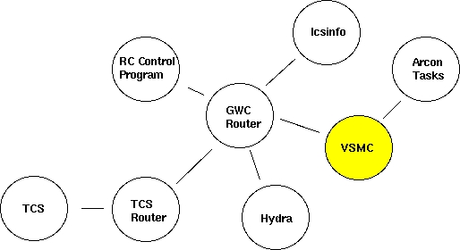
The Arcon task open a client connection to the VSMC program and send a string command that the VSMC routes through the GWC router to the different GWC clients (RC-Spectrograph Control Program, TCS Router, Hydra Control Program). The result of the operation is then sent back to the Arcon task. In such a way Arcon is now capable of communicating with many devices and still appear to have a single SMC to talk to.
back to top [31]
The Arcon API to talk to the VSMC (and to talk to any other SMC) lives in /xp/iraf/arcon/lib/motors/Drivers. It consists of several files that implement the SMC communication protocol over different communication channels. The current incarnation of the API includes support for communication through serial ports, TCL/DP channels, TCP sockets and RPC.
Selection of protocol is made by setting the "protocol" environment variable in the instrument_taks.cl file specific to each instrument. For the RC-Spectrograph the instrument_tasks.cl file lives at /xp/iraf/arcon/hardware/ctio/instruments/cs4m and the environment variable is called "lsi_protocol". This variable has to be set to "tcldp" to talk with the virtual SMC. The "lsi_host" variable must be set to the machine in which the VSMC program is running and the "lsi_port" variable has to be set to the port in which the VSMC is listening for connections that is port 2002.
back to top [31]
The VSMC software code lives at /xp/source/sun/vsmc. The structure of the directory tree is as follows:
vsmc
bin
doc
lib
bitmaps
vsmc
share
include
lib
src
api
gwcwish
The VSMC software consist of an extended TCL/TK interpreter plus a set of TCL/TK scripts that build the functionality required by the application. The extended TCL/TK interpreter lives at sub directory "src/gwcwish". Support is provided for compiling the interpreter under Linux, SunOs and Solaris. The TCL/TK scripts live at sub directory lib/vsmc.
Usually the VSMC program will automatically start as part of the RC-Spectrograph setup done by the "SetFiles -a" command. The SetFiles command allows to choose the instrument in use which in turn makes Arcon execute the specific instrument_init.cl script for that instrument to launch the VSMC program. Still it is possible to launch the program manually by typing "start_vsmc" in the Iraf command line. Arcon is also in charge of shutting the program down when Arcon is closed or restarted.
The startup script will search the /xp/source/sun/vsmc/bin directory for file "vsmcrc" to set the environment before running. If not found it will look for the default version of that file at the user home directory. Following is the vsmcrc file that actually lives at /xp/source/sun/vsmc/bin
---------------------------------------------------------------
# Environment variables
# Source the mosaic environment
source /usr/local/gwc/config/mosaic.env
# Environment variable for the VSMC home directory
setenv GCLIENT_HOME /xp/source/sun/vsmc
# Home directory of the TCL/TK library
setenv TCL_LIBRARY $GCLIENT_HOME/share/lib/tcl8.0
setenv TK_LIBRARY $GCLIENT_HOME/share/lib/tk8.0
setenv TIX_LIBRARY $GCLIENT_HOME/share/lib/tix4.1
setenv DP_LIBRARY $GCLIENT_HOME/share/lib/dp4.0
# The MPG_ROUTER variable designates the name of the host in which
# the router run. When not defined the the mpg router is supposed
# to be running in indus.tuc.noao.edu.
# Here commented out to use the definition in mosaic.env
#setenv MPG_ROUTER ctioa1
# The variable MPG_ROUTER_PORT designates the port in which the mpg
# router is listening for incoming connections. The default value
# for this variable is 1 plus the the wiyn router port (2345).
# Here commented out to use the definition in mosaic.env
#setenv MPG_ROUTER_PORT 2347
# This tell the program where to find the binaries and configurations file.
setenv GCLIENT_BIN $GCLIENT_HOME/bin
setenv GCLIENT_LIB $GCLIENT_HOME/lib
# Make sure that guidebin is in the search path
set path = ( $GCLIENT_BIN $path )
# Make sure we have the right man path
if ($?MANPATH) then
setenv MANPATH {$MANPATH}:$GCLIENT_HOME/man
else
setenv MANPATH {/usr/man}:$GCLIENT_HOME/man
endif
# Uncomment this line if running in SunOs environment
setenv LD_LIBRARY_PATH /usr/lib:/usr/local/X11R5/lib:/usr/openwin/lib
---------------------------------------------------------------
back to top [31]
The graphic user interface of the VSMC program allows the user to check for resent requests and their result as well as for the current status of the communication link to the GWC router.
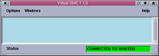
When the application starts it opens a connection to the GWC router. Then it publish some GWC command variables. Incoming Arcon request are logged into the logging panel along with a time stamp and a correlative number.
The menu bar has three menus: Options, Windows and Help.

Use the options menu to activate/deactivate the alarm bell and to quit the application. When selected the alarm bell flag activates an audible tone to signal that the communication link to the GWC router is broken.

Use the windows menu to pop up the console window and the comparison lamps interface.
back to top [31]
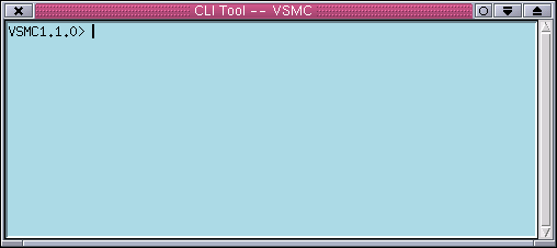
Use the console window to type string commands to control the RC-Spectrograph, the comparison lamps and the rotator mirror. The only command available is rcspec. The available subcommands and arguments are listed below.
rcspec all
return the current status of the RC-Spectrograph plus other devices. The order of the fields is as follows: complamp, rotator mirror, comparison lens, slit width, decker, grating tilt, collimator focus, upper filter position, lower filter position, mask position, sky suppresser position, rear slit viewer
rcspec colfocus [move|position|status|stop] value
Interface to the collimator focus mechanism.
rcspec clamp move [on|off]
Turn the old comparison lamps on or off.
rcspec complamp [move [etalon|tha|qua|hene|pen|off|park] | position | status | stop]
Command interface to the hydra comparison lamps system.
rcspec complens [move|position|status|stop] value
Command interface to the comparison lens mechanism.
rcspec lfilter [move|position|status|stop] value
Command interface to the lower filter.
rcspec mask [move|position|status|stop] value
Command interface to the newall mask mechanism.
rcspec rotatormirror [move|position|status|stop] value
Command interface to the rotator mirror.
rcspec slitwidth [move|position|status|stop] value
Command interface to the slit width mechanism.
rcspec tilt [move|position|status|stop] value
Command interface to the grating tilt mechanism.
rcspec ufilter [move|position|status|stop] value
Command interface to the upper filter mechanism.
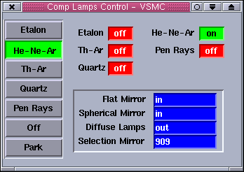
The lamps window allows the user to turn the comparison lamps system on/off and to select the comparison lamps sources.
When no motion is sensed, the status labels are blue and white. When a mechanism is active or moving the status labels blink and the background color goes yellow to reflect the new status. If no status information is available or an error condition is sensed the status labels blink and the background goes red.
back to top [31]
The logging area shows all the incoming requests to the VSMC and the exceptions that have occurred during the session. All messages are prefixed with a time stamp and a correlative number. Use the scroll bar to move across the log messages.
The status bar presents the current status of the communication link to the GWC router. When the link is broken the status label will go red and will start blinking signaling that the communication has been lost. After that, the program will start a reconnection sequence trying to connect every ten seconds to the GWC router.
"ERROR: generic client can't connect to GWC ROUTER..." - Check that the GWC router is actually running on its host machine.
If its running check that the machine in which the VSMC is running is an enabled machine. Check the /usr/local/gwc/config/routersetup.tcl file for your machine name. If not present add the name using the rest of the file as a template.
Check also that the environment variables MPG_ROUTER and MPG_ROUTER_PORT are set to the proper values in the vsmcrc file.
"WARNING: generic client not connected to GWC ROUTER..." - This warning message appears to warn the user he chose not to
connect to the GWC router.
"ERROR: illegal command: rcspec ..." - You type an unknown command. Check the list of legal commands above in this document.
back to top [31]
Last Updated: March 5, 2001
rcantaruttiATnoao.edu
| Contents: | |
| 1. | Architecture [31] |
| 2. | IcsInfo Software [31] |
ICS Info (Rev 1.0 March 2001)
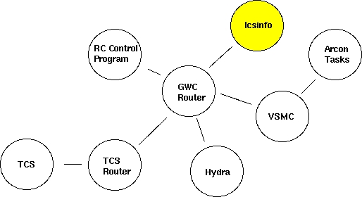
Arcon requires set up information from the instrument to fill the image headers produced with each Arcon exposure. To get the header information Arcon reads the appropriate header file generated by a GWC router client called icsInfo. Icsinfo is a configurable header information server that collects the header data from different sources through the GWC router and writes it down to a file which is read by Arcon at the end of every exposure. The picture below illustrates this architecture.
back to top [31]
The icsInfo is a TCL script that starts up automatically at Arcon boot time. The script runs forever waiting for Arcon requests to write down a header information file in the /tmp directory. The information included in that file depends on configuration files specific for each instrument.
The icsInfo source code lives at /a1xp/source/sun/icsInfo directory. The directory structure is as follows:
The icsInfo software consist of an extended TCL interpreter that runs a single TCL script. The extended TCL interpreter lives at directory icsInfo. Support is provided for compiling the interpreter under SunOs only. The TCL script lives at directory icsInfo as well.
Usually the icsInfo program starts automatically as part of the Arcon configuration set up of the instrument. The program is launched from the instrumet_init.cl Iraf script. Still it is possible to start the program manually by typing start_cs4m_info (RC-Spectrograph) at the Iraf command line.
The program will then look for the configuration files specific to the instrument in the icsInfo/Config/cs4m (RC-Spectrograph) directory. The configuration files are headers.conf and telem.conf. The file headers.conf lists the different GWC variables that icsInfo will subscribe to in order to receive header information of the instrument. The file telem.conf defines the appearance of the header file to be generated (keyword name, comments and position)
Once running the program it will present a prompt at which the user can type TCL commands. A very useful command is "fillheader". This command will dump to the screen the header file including the most resent data available.
Note: Replace the word cs4m with the arcon name of the instrument you are using. For example if you are using hydra the start up command will be start_hydra_info and the configurations files will be at icsInfo/Config/hydra.
back to top [31]
Last Updated: March 5, 2001
rcantaruttiATnoao.edu
The R-C grating spectrograph is used at the f/7.8 R-C focus of the 4.0-meter telescope where the scale is 6.56 arcsec/mm. It is identical to the one at Kitt Peak National Observatory, in construction and as far as possible, in operation. The distinguishing feature of these 4.0-meter spectrographs is their large beam size. As a result, higher dispersion than usual for Cassegrain spectrographs is available, along with excellent spatial resolution for observations of extended objects. All functions of the spectrograph can be controlled remotely by the data acquisition computer, permitting convenient and efficient operation.
In normal operation, slit viewing is accomplished by means of a TV mounted on the instrument rotator. Two positions of the instrument rotator mirror carriage provide for direct viewing of the field, for target acquisition and for viewing light reflected from the spectrograph slit. The field of view in slit viewing mode is somewhat restricted, so that only the central arc minute of the spectrograph slit is visible on the TV. Auto guiding is normally accomplished using a separate TV camera, optically coupled to the offset guide probe, mounted in the instrument rotator, in conjunction with a leaky guider module. It is also possible to connect the same leaky guider to the slit viewing TV in order to permit auto guiding on light reflected from the slit jaws. Full details of the acquisition TV system and auto-guiders can be found in Section III. The spectrograph itself has both front-slit and rear-slit viewing optics.
The spectrograph may be rotated by up to 180 under remote control from the console room, with the telescope in any position. Observer support personnel should be notified of your intention to do so at the start of your run so that they can ensure that all cables have been routed to permit this. Normally the spectrograph is mounted with the slit E-W (PA=90 ).
The optical diagram for the spectrograph is given in Figure IV-1. The following descriptive sections are listed in the order which light passes through the spectrograph.
The decker plate for defining the length of the slit has five stellar/comparison pairs, a pointer for marking the center of the slit, a position for holding a calibration wedge, and a fully open position. The relevant dimensions are listed in Table IV-1.
The entrance slit has a length of 50 mm. Its width has a range from closure to 50 mm. One second of arc corresponds to approximately 150 microns. The size of the slit projected on the detector can be calculated from the information given in Figure IV-2. The conventional slit can be replaced by an aperture plate, permitting the acquisition of spectra of several objects distributed over an approximately 5 arcmin diameter field. Aperture plates are currently prepared in advance at NOAO Tucson. A TV camera can be attached to the rear-slit viewing periscope to assist in registering the apertures with the program objects. Observers with a potential interest in this system should contact CTIO staff well in advance of their run.
The multiple aperture plate contains 55 holes each 150 wide (1 arcsec) at 1.0 mm (6.6 arcsec) intervals along the slit. Exposures of the quartz lamp or white spot taken through these multi-holes are used to calibrate the geometric distortions introduced by the detector/camera combination for long slit work.
Two filter bolts are available each containing four filters plus a clear position. The lower filter bolt always contains neutral density filters; the upper-filter bolt either contains further neutral density filters or order sorting filters. An additional holder to contain a single order sorting filter can be manually placed in the beam if required. Note that this can only be done with the image tubes turned off if the 2D-Frutti is in use. Since all these filters are below the slit, the appropriate filters should be in place when the spectro- graph is focussed. The available filters are listed in Table IV-2.
A four-position plate acts as a shutter and Newall mask. The positions are: open, closed, mask north half and mask south half. The latter two are used for quantitative focusing of the spectrograph. Successive exposures of a comparison source are taken through each mask. At perfect focus, the positions of the arc lines in these exposures coincide exactly. Increasing departures from focus lead to greater displacements between the images. An additional high speed computer controlled shutter is used to obtain precisely timed exposures.
The collimator mirror is an off-axis paraboloid of 225 mm diameter and 1161 mm focal length. The point-source beam size is 152 mm. The collimator has a travel of 38.1 mm for focusing the image of the slit onto the detector.
At present, there are thirteen 203 by 254 mm gratings available. Their nominal specifications are listed in the Table IV-3. Table IV-4 lists the resolution and coverage available with various detectors. Tables IV- 5, IV-6, and IV-7 list grating efficiencies.
Two Air Schmidt cameras are available. The Air Schmidt camera is a field-flattened Schmidt camera of 229 mm focal length and 229 mm clear aperture. This camera is exclusively used with a CCD detector, which together with its special dewar, forms an integral part of the camera. All optical surfaces of the "red" Air Schmidt are coated to give optimal performance in the red and as a result, this camera cannot be used blueward of 4500 , the "blue" Air Schmidt can be used at all optical wavelengths (3000 - 10000 ) but is less efficient that the "red" Air Schmidt redward of 5000 .
The Folded Schmidt camera is also a field-flattened Schmidt camera with 229 mm focal length and optical characteristics almost identical to the Air Schmidt. The corrector is optimized for blue and near UV wavelengths. The incorporation of a folding flat in the optical train brings the focal plane outside the body of the camera, permitting its use with the 2D-Frutti photon counting system or the CCDs mounted in standard "direct" dewars. This causes the camera to have somewhat less clear aperture and consequently greater vignetting than the Air Schmidt. On-axis, the Folded Schmidt has nearly the same throughput as the Air Schmidt. For distances of greater than 10 mm off-axis, the through-put begins to fall off significantly. The uv transmitting optics provide for excellent throughput at wavelengths all the way down to the atmospheric cutoff.
Two calibration sources, Th-Ar and He-Ne-Ar, are mounted in the instrument rotator. It is possible to turn on the He-Ar and the Ne lamps separately. A quartz continuum lamp for flat-field calibration is also available. With a manually operated filter bolt in the rotator, it is possible to attenuate the comparison source light by a factor of either three or ten. A lens is moved over the slit of the spectrograph to provide an f/7.6 beam for comparison exposures.
Links
[1] http://www.ctio.noao.edu/noao/content/loral-3k-arcon35-4m-r-c-spectrograph
[2] http://www.ctio.noao.edu/noao/content/instrument-control-software-blanco-rc-spectrograph
[3] http://www.ctio.noao.edu/noao/content/4mrc-virtual-smart-motor-controller
[4] http://www.ctio.noao.edu/noao/content/4mrc-ics-info
[5] http://www.ctio.noao.edu/noao/content/4m-rc-basic-optical-characteristics
[6] http://www.ctio.noao.edu/noao/sites/default/files/instruments/spectrographs/control_panelp.gif
[7] http://www.ctio.noao.edu/noao/sites/default/files/instruments/spectrographs/grating_setupp.gif
[8] http://www.ctio.noao.edu/noao/sites/default/files/instruments/spectrographs/extract%20positionp.gif
[9] http://www.ctio.noao.edu/noao/sites/default/files/instruments/spectrographs/enable_rc_motorp.gif
[10] http://www.ctio.noao.edu/noao/sites/default/files/instruments/spectrographs/initializep.gif
[11] http://www.ctio.noao.edu/noao/sites/default/files/instruments/spectrographs/Writer_rc_parameterp.gif
[12] http://www.ctio.noao.edu/noao/sites/default/files/instruments/spectrographs/sv14114142.jpg
[13] http://www.ctio.noao.edu/noao/sites/default/files/instruments/spectrographs/sv14114151.jpg
[14] http://www.ctio.noao.edu/noao/sites/default/files/instruments/spectrographs/sv14114149.jpg
[15] http://www.ctio.noao.edu/noao/sites/default/files/instruments/spectrographs/sv14114146.jpg
[16] http://www.ctio.noao.edu/noao/sites/default/files/instruments/spectrographs/sv14114153.jpg
[17] http://www.ctio.noao.edu/noao/sites/default/files/instruments/spectrographs/sv14114155.jpg
[18] http://www.ctio.noao.edu/noao/sites/default/files/instruments/spectrographs/sv14114159.jpg
[19] http://www.ctio.noao.edu/noao/sites/default/files/instruments/spectrographs/sv14114163.jpg
[20] http://www.ctio.noao.edu/noao/sites/default/files/instruments/spectrographs/sv14114165.jpg
[21] http://www.ctio.noao.edu/noao/sites/default/files/instruments/spectrographs/sv14114167.jpg
[22] http://www.ctio.noao.edu/noao/sites/default/files/instruments/spectrographs/sv14114169.jpg
[23] http://www.ctio.noao.edu/noao/sites/default/files/instruments/spectrographs/sv14114171.jpg
[24] http://www.ctio.noao.edu/noao/sites/default/files/instruments/spectrographs/sv14114173.jpg
[25] http://www.ctio.noao.edu/noao/sites/default/files/instruments/spectrographs/sv14114179.jpg
[26] http://www.ctio.noao.edu/noao/sites/default/files/instruments/spectrographs/sv14114181.jpg
[27] http://www.ctio.noao.edu/noao/sites/default/files/instruments/spectrographs/sv14114189.jpg
[28] http://www.ctio.noao.edu/noao/sites/default/files/instruments/spectrographs/sv14114183.jpg
[29] http://www.ctio.noao.edu/noao/sites/default/files/instruments/spectrographs/sv14114185.jpg
[30] http://www.ctio.noao.edu/noao/sites/default/files/instruments/spectrographs/sv14114187.jpg
[31] http://www.ctio.noao.edu/noao