 [1]The Víctor M. Blanco 4-m Telescope was commissioned in 1974. It is a near twin of the Mayall 4-m telescope on Kitt Peak. The wide field of the Blanco 4-m telescope uses the wide field camera, DECam [2], and the low-intermediate resolution spectrograph COSMOS [3], to complement the high resolution capabilities of SOAR and GEMINI.
Internal only telemetry plots (depend on availability of DECam):
| Radius of curvature | 21311.6 mm concave |
| Conic constant | -1.09763 |
| Mirror diameter | 4022.9 mm (see CH2150.260-A001) |
| Bare mirror clear aperture | diam 3965.4 mm |
| Central hole | diam 1317.8 mm |
| Used clear aperture | diam 3934 mm (August 00 after installation of seal CH2922-A001) |
| Central obscuration | diam 1651 mm (PF cage baffle for f/8 M2) |
| Light-collecting area | 10.014 m^2 |
| Distance from primary | 7494.25 mm |
| Radius of curvature | 9569.6 mm convex |
| Conic constant | -5.2625 |
| Clear aperture | diam 1295.4 mm |
| Distance from primary | 8.6212e03 mm |
| Radius of curvature | 4.9865e03 convex |
| Conic constant | -3.044206 |
| Clear aperture |
| Distance from primary | 9.6871e03 mm |
| Radius of curvature | 2.1153e03 convex |
| Conic constant | -2.8056 |
| Clear aperture: |
Prime Focus f/2.87.
Plate scale = 18.0 arcsec/mm or 0.26"/15micron pixel
The only instrument currently available (2012 onwards) at Prime Focus is the Dark Energy Camera [18], follow the link for details.
Ritchey-Chretien (RC) Focus f/8.
Plate scale = 6.56 arcsec/mm
The only instrument currently available at f/8 is COSMOS (Cerro Tololo Ohio State Multi-Object Spectrograph [3]).
This focus is surrounded by a roughly hemispherical Cassegrain Cage. It is equipped with an instrument rotator and offset guider as standard equipment. (WARNING: The rotator may not be functional with all instruments due to interference between the instrument and the surroundings in the Cassegrain Cage.) User supplied instruments may be attached on either the rotator directly or the guider. The nominal focal plane is at a position 6" (15.24 cm) below the Guider mounting surface. The Cass. Cage is entered by means of a walkway that is normally used when the telescope is at the zenith position. Power (110v, 60Hz) is available from an uninterruptible source.
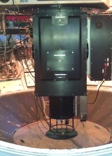
DECam [19] is a high-performance, wide-field CCD imager mounted at the prime focus of the Blanco 4-m telescope at CTIO. DECam imager contains 62 science CCDs with 520 megapixels and images 3 square degrees (2.2 degree wide field) at 0.263 arcsecond/pixel resolution.
COSMOS [3]is the CTIO Ohio State Multi-Object Spectrograph, an imager and low- to moderate-resolution spectrograph covering from approximately 3500 Å to 10000 Å. COSMOS has an approximately 10 arcminute circular field of view, at a scale of 0.29” per pixel.
COSMOS - Cerro Tololo Ohio State Multi-Object Spectrograph
COSMOS is a nearly-identical modified version of the OSMOS spectrograph in use on the MDM Hiltner 2.4-m telescope, and adapted for use on the 4-m telescopes at CTIO. The design modifications, fabrication, assembly and testing were a joint effort between Ohio State and NOIRLab. This instrument was built to provide a modern, high-efficiency spectrograph for the U.S. community that meets many of the scientific needs described in the ReSTAR (Renewing Small Telescope for Astronomical Research) report.
General Information:
Observing Information and Tutorials:
Calibration Information:
Data Reduction Guides:
Older Links:
Last Updated: 09 March 2018 (SDP)
DECam is a high-performance, wide-field CCD imager mounted at the prime focus of the Victor M. Blanco 4m Telescope at CTIO, with 62 science CCDs (60.5 useful) with 520 megapixels and images 3 square degrees (2.2 degree wide) field at 0.263 arcsecond/pixel resolution. DECam is a facility instrument, available to all users. DECam was built to carry out the Dark Energy Survey [35] (DES) Project by the DES Collaboration, which finished observations in January 2019. We can accommodate programs from small to large, and also those with special requirements such as synoptic and target of opportunity. Most of the programs fit within a "half night" organization, which provides a better match of program requirements to lunar phase than does whole night scheduling. Note that observations are taken "classically", with astronomers present at the telescope, although we can also under pre-arranged conditions support remote observing from a permanent and tested remote observing facility. We do not offer queue observing. Please do not hesitate to contact us! (decam-help@ctio.noao.edu [36]).
OBSERVING HELP:
DATA:
USEFUL LINKS:
IMPORTANT!
NEWS:
CTIO Contacts
_________________________________________________________________
CTIO DECam Support Pages [82] (Internal Use Only)
DECam PropIDs & Special Cases [83] (Internal Use Only)
DECam Log of Configuration Changes and Events [84] (Internal Use Only)
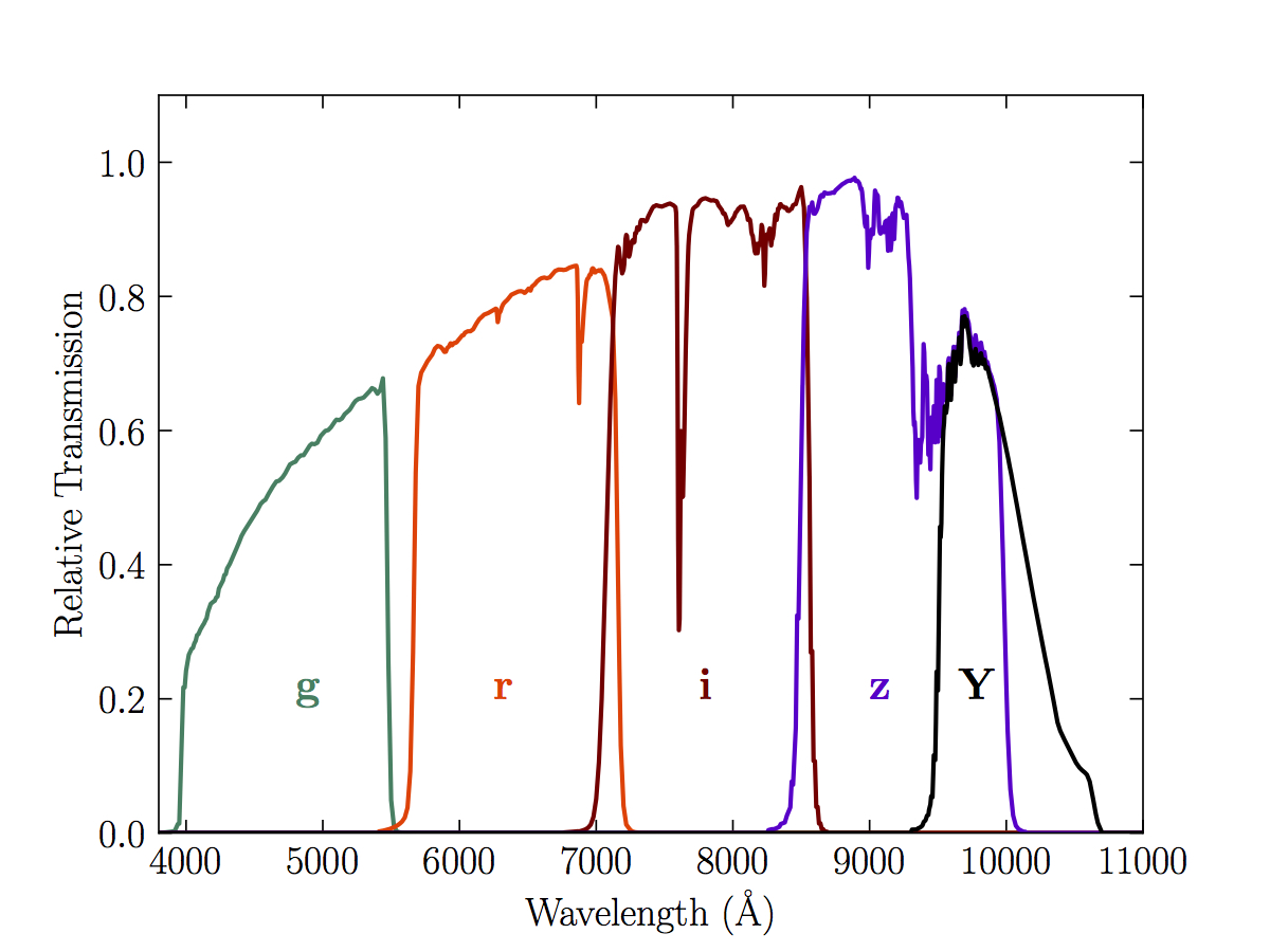
DES DR1 Standard Bandpasses for the DECam g, r, i, z and Y filters. The bandpasses represent the total system throughput, including atmospheric transmission (airmass = 1.2) and the average instrumental response across the science CCDs.
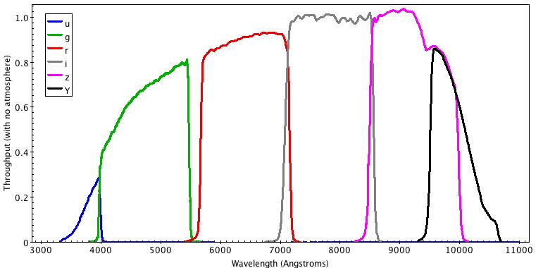
DECam filters ugrizY throughput (with no atmosphere)
Format for TCS Coordinate Files
This is the format definition for object catalog coordinate lists for use with the Víctor M. Blanco 4-meter Telescope control system. Such files can be prepared before the run and can be loaded into the TCS at the time of the run.
MyObjectName HH:MM:SS +/-DD:MM:SS Epoch ppRA ppDec
MyObjectName is one word, no spaces.
No spaces between +/- sign and DD.
Each line must be less than 79 characters long.
The file must be less than a total of 64Kbytes.
pmRA,pmDec are proper motion in arcsec/yr.
Field separators are one or more spaces.
Sample data (without pmRA,pmDec):
|
Object |
RA (J2000) |
DEC (J2000) |
|
| SA113 | 21:41:14.00 | +00:42:00.0 | |
| TPHEc1 | 00:31:05.00 | -46:22:43.0 | |
| TPHEc4 | 00:30:30.00 | -46:09:00.0 | |
| SA92c1 | 00:55:07.00 | +00:38:56.0 | |
| SA92c2 | 00:53:47.00 | +00:38:56.0 | |
| SA92c3 | 00:53:47.00 | +00:58:56.0 | |
| SA92c4 | 00:55:07.00 | +00:58:56.0 | |
| PG0231c4 | 02:33:41.00 | +05:38:40.0 | |
| SA95c | 03:53:21.00 | +00:19:40.0 |
The Víctor M. Blanco 4-meter Telescope, also known as Blanco telescope, has an equatorial mounting. Due to this the telescope cannot point everywhere.
The next figure shows the area of the sky visible to Blanco telescope (grey area) and the area of the sky that can not be observed (red grid).
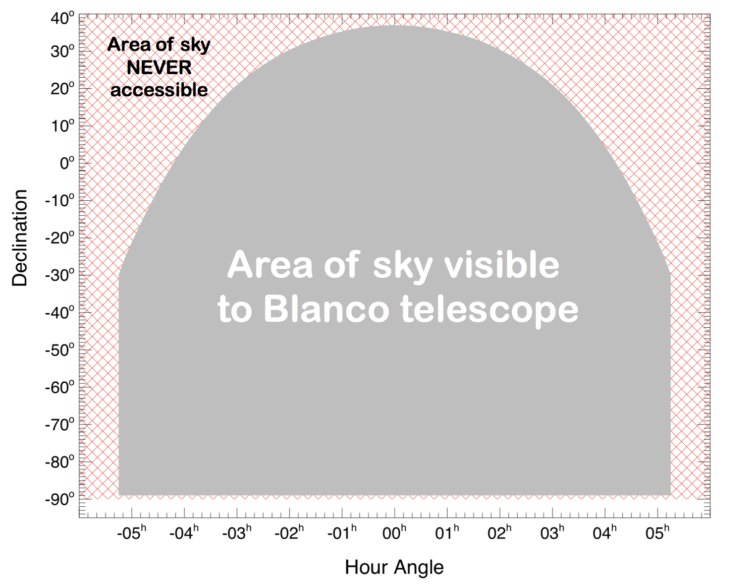
The Blanco operational range is delimited by the following values of hour angle (HA) and declination (Dec):
| HA [hh:mm:ss] | Dec [deg] |
| 00:00:00 | 37 |
| +/-01:06:00 | 35 |
| +/-02:03:36 | 30 |
| +/-02:38:24 | 25 |
| +/-03:04:48 | 20 |
| +/-03:25:48 | 15 |
| +/-03:43:12 | 10 |
| +/-03:58:48 | 5 |
| +/-04:12:36 | 0 |
| +/-04:25:12 | -5 |
| +/-04:36:36 | -10 |
| +/-04:47:24 | -15 |
| +/-04:57:36 | -20 |
| +/-05:07:12 | -25 |
| +/-05:15:00 | -30 |
| +/-05:15:00 | -35 |
| +/-05:15:00 | -40 |
| +/-05:15:00 | -45 |
| +/-05:15:00 | -50 |
| +/-05:15:00 | -55 |
| +/-05:15:00 | -60 |
| +/-05:15:00 | -65 |
| +/-05:15:00 | -70 |
| +/-05:15:00 | -75 |
| +/-05:15:00 | -80 |
| +/-05:15:00 | -85 |
| +/-05:15:00 | -89 |
However, it is recommended not to point to:
or
due to the risk of the mount crossing -89d or +39d (respectively) while tracking due to small perturbations.
Detailed information may be found here [95].
The telescope's pointing is refined via a pointing map in which we periodically scan the telescope over the whole sky and measure the offset between where the telescope thinks it's pointing and what we see with DECam. This map of offsets is interpolated and applied to the telescope pointing on each subsequent pointing. Of course, there is always noise present and the map will tend to drift slightly over time (not least because, for example, the telescope "breaths" with temperature variations). As a result, long range slews will tend to have larger errors than short range slews.
Typically, watching the same field all night, the Blanco's pointing accuracy is good to 10-20", maybe 5" rms on a good night, relative to your starting zero point. This accuracy will tend to drift during the night and we recommend that those who really care about that accuracy reset their zero point every now and then and especially after a long slew.
The two charts below show the run pointing and offsets during a typical night. Note an overall ~20" smooth variation with a few arcsec of noise superimposed, plus a large excursion just before 05:00. That large excursion was associated with a change in field, but two additional, indeed larger, such changes later in the night showed no such large excursion in offsets. Which slews will generate large offsets is not trivial to predict.
Note that the pointing map is made down to within ~30 degrees of the horizon. Above this altitude, corrections are interpolated, below this altitude they are extrapolated from the lowest edge of the map and are concomittantly uncertain.
With DECam, resetting the zero point requires an exposure of a few seconds, analysis using the Kentools "center" command, and instructing the operator to input the new offsets, and repoint. This whole exercise will take a couple of minutes. The result will not be perfect.


Revised A.R. Walker July 14 2020
Written in November 2000.
Up to a few years ago, there were traditionally 2 kind of paints used to cover telescope domes: 'Lomit' and titanium oxide.
Lomit is the grey-looking (silver- or aluminium-like) paint. It typically overheats by up to 20degC during the day in the sunshine and overcools by about 2degC at night after reaching equilibrium with ambient air (delay due to thermal inertia of structure).Its emissivity is 0.21.
Titanium oxide is the white paint which had, for example, always been in use at CTIO. It typically maintain thermal equilibrium with ambient air during the day (no overheat) but overcools by about 5degC during the night. Thus, although titanium oxide is far better than Lomit during the day, it is slightly worse at night, and the air cooling around the dome tends to fall/roll down off the walls and eventually enter the dome through the shutter or the lateral doors, eventually causing dome seeing. It is frequent in summer time on Cerro Tololo to see the domes wet while the RH is only 75%: this is because the outside skin of the domes overcools several degrees below ambient and can drop below the dew point.
In the early nineties, our colleagues at Las Campanas Observatory have used an aluminium sticky foil to cover their domes and got very positive results (more recently they used it for the Magellan twin telescope domes). Our measurements have shown that, with such a coating, the dome typically overheats by 5degC during the day and by about 2degC during the night. It has therefore better characteristics than the 2 older techniques.
Summary:
The difference with the Lomit paint (both are greyish and reflectivish) is mainly that the foil is made out of an insulating layer of adhesive about 0.12mm thick (5/1000") coated with aluminium. Consequently there is no direct thermal contact between the ambient air and the metallic structure of the dome (thus avoiding the diurnal overheating). The product is called Compaq #804 Aluminium foil tape, it comes in rolls of 30"x60yds and it is sold by Bron tapes Inc. Adhesion is increased by application of a primer on the substrate, and is good enough that no maintenance is required over periods as long as 7 years. The foil can also be washed without deterioration.
Our hope is therefore to improve the thermal performance of the 4m dome and decrease dome seeing. New temperature sensors with RF transmitters and receivers will be mounted on the dome (which is a rotating part!) to attempt quantifying these modifications.
M.B., 14th November 2000
Last updated July, 2020
The Víctor M. Blanco 4-meter Telescope Environmental Control System has more than 80 parameters (Table 1) collected by more than 69 sets of sensors (Table 2) and 27 ethenet telemetry modules (Table 3). The telemetry system is located from Glycol Pumps to the very top of the Blanco dome.
Several sensors (or instruments) can be connected to one ethernet telemetry module, and one sensor can measure one or more parameters.
The parameters are air temperatures, surface temperatures, fluid temperatures, humidity, air pressure, oil pressure, glycol flow, voltages and more.
A Python script runs on the telemetry machine getting sensor data from the telemetry modules and sending to the MariaDB database server for ECS (Fig 1).

Fig 1: Database structure for ECS (includes telemetry and control)
The data is updated every minute on DB tables and it is displayed on web depending on the area of Blanco Telescope (Fig 2).

Revised 13 July 2020 by A. R. Walker.
Original by Maxime Boccas, 18 October 1999.
Over the period 1993-2000, many improvements have been carried out at the Víctor M. Blanco 4-meter Telescope to improve its image quality. The principal changes are: an active primary mirror support with lookup tables, a refigured f/8 secondary mirror, an image analyzer for the Cassegrain foci, removal of most heat sources inside the dome, control of the dome temoerature during the day using the AHUs and heicopter fan, active ventilation (air sucker) of the primary cell at night, dome ventilation doors and active control of oil temperature. The dome outer surface is covered with insulated aluminum panels which although the outer surface heats up during the day mpre than the originbal Lomit paint, does not over-cool at night..
Since 2012, DECam at Prime Focus has introduced a 5-axis hexapod (x,y,z, tip, tilt) position of the instrument and corrector, driven by a Look Up Table and tweaked on an exposure by exposure basis by a wavefront sensor that analyses out-of-focus inages, and makes a "tweak" to the hexapod position.
The night assistant must check that all the environmental control functions explained below are working properly during the night.
1.1 General closure conditions:
ABSOLUTE closure when:
Dome re-opening:
GUIDELINE :
BEWARE PLEASE: Don't permit observing beyond these limits! If you have trouble to be heard by the astronomer, please REPORT it (so we can politely explain the rules).
The dome AND the mirror cover have to be opened 1 hour before sunset, orienting the shutter eastward to make sure no direct sunlight will enter the dome. Dome and mirror cover have to be closed at the end of the night.
1.3. Lateral sliding doors opening:
These doors have to be opened at sunset and left opened all night.
The Primary mirror cooling system has from 2019 been activated only in "sucking" mode, all the time, day and night. That is,we do no longer blow cold air onto the primary.
During the night, you are invited to check Blanco ECS Telemetry [106] and check that:
1.5. Floor cooling, Dome Air Handling Units (AHUs), and stirring fan on main floor (M):
The cooling of the C floor and M floor in the dome is always ON. It is currently regulated automatically.
The two AHUs should always be off when the dome is open. There is no automatic control, Thus the procedure is for the telescope operator to turn green on at the end of the night, and then Telops staff evaluate the inside versus outside temperature and the weather forecast prediction for the following night, then decide whether to turn off one or both, and at what time.
BEWARE: In conditions of high humidity the AHUs can ice up and restrict the air flow, This condition can be cleared rapidly by turning off the cooling, air flow on.
The large stirring fan (helicopter) on the M floor (inside the dome) should always be ON when the dome is closed and OFF when the dome is opened. This fan improves greatly the air circulation inside the dome.
SAFETY: Both the AHUs and the helicopter can be turned off during instrument changes or any other works around the telescope if the noise is a safety concern, e.g. by impeding communication. But don't forget to turn them back on when you are done!
The cooling of the oil circulating under the R.A. rear and front pads is activated automatically when the pumps are turned ON by Observer support at sunset. The oil glycol valve is controlled (range is 1-2.25 V) by an equation involving the low dome and oil glycol temperature sensors. It is important that the oil cooling be working: if it is not, you can diagnostic it in ECS Telemetry [106] (the "before pad" and "glycol" entries on the OIL line will quickly indicate around 30°).
The oil temperature for the Hidrostatic Bearings must be between 8 to 10C.
1.7. Chimney fans: Not in use.
These fans are located inside the chimney at the level of the primary mirror and suck ambient air into the mirror cell so as to form a laminar downward flow in the chimney. This is to prevent Cass cage heat sources from creating convection in the light path in the chimney.
At Cassegrain foci (f/8), Observer Support has to turn ON the chimney fans before sunset. The switch is on the power supply on the old console room desk. The night assistant must turn it OFF at the end of the night.
At Prime Focus: The top of the chimnney is covered with a cap.
The current thermal plan in the building is not changed. Always leave the air conditioning at full power. Do not use heat sources at level M, MZ and C. Always maintain the doors closed in the passageways (especially the glass door in front of the lift at GR floor, the cryocooler compressor and pump rooms). In general, respect the signs in the building.
2. Brief reminder of known optical problems
The image quality of the telescope can suffer deterioration mainly from 3 optical problems:
Note: IMAN is normally used only on engineering nights.
This is due to tiny slippage of M1 and/or deformation under its own gravity. Astigmatism will show up as elongated images, perpendicular on each side of the focus, especially for large H.A. (typically more than 2 hours). We compensate that with a lookup table, which controls the pressure in the air bags under M1. Thus the TCP toggle "CORR" should always be ON, at all foci. Note that if the F/8 secondary mirror lose its vacuum, strong astigmatism will immediately show up (typically 2-4 microns as measured by iman).
This aberration shows up in 2 cases: at Prime Focus if the primary mirror axis is not aligned with the instrument and in the 2-mirror configuration (f/8) when there is a misalignment between them. Coma produces images with a flare (a tail like a comet) which is identical (same amplitude and direction) on each side of the focus.
At Prime Focus coma is controlled by the DECan active optics system and Look Up Table that control the hexapod on which the instrument is mounted.
Coma usually increases the further you go from the optical axis -this is called "field coma" and is normal (it is always supposed to be 0 on axis)- and also shows up when the optical axis of M1 and M2 are not coaligned -this is called "decentering coma" and is abnormal-. Our f/8 is a Ritchey-Chretien (RC) type, which means it is optically designed to correct the field coma. If the telescope is properly aligned there should not be any visible coma at f/8. If coma shows up anywhere in the field (it would usually be constant all over the field), there is a mirror misalignment and this can be corrected by using IMAN.
Thermal expansion that can occur at night will cause the telescope to defocus. The prime focus changes at a rate of -110 microns/°C, the f/8 focus at -780microns/°C. The actual movement of He f/8 mirror is a factor 10 less (i.e. -78 microns/°C). The auto[focus of DECam means you do not have to worry about focus at prime focus.
Use Blanco ECS Sensors Diagram [104] to check the Serrurier truss temperature and adjust the focus accordingly (F/8).
3. Prime Focus nights:
Focus decreases by 110 units per 1° increase in temperature.
4. f/8 nights:
* CORR ON all the time.
* M2 Corrections ON all the time
* Temperature drift compensation:
Focus number increases when focal plane (and M2) moves up
The focus number represents microns of motion of the focal plane (not of M2)
Decrease focus setting 780 units per 1° increase in temperature
*Collimation:this has to be checked according to the following procedure:
Each material has its own radiation cooling property (which is not easy to calculate by the way). Just know that if there is no wind, the radiation cooling is low and surfaces will not equilibrate thermally with the ambient temperature very quick. Also, a surface, even with moderate ability to radiate, looking into a "cold" sky can cool down several degrees below ambient temperature. Fortunately, a mirror radiates very little. Nevertheless, when cooling the mirror during the day, the mirror temperature is usually several degrees below ambient temperature and there are risk of condensation. The control loop will turn off the cooling when the difference between the mirror temperature and the dew point shrinks to only 2 degrees.
Knowing the Relative Humidity (RH in %) and the ambient temperature (Ta) of the air, one can calculate the dew point temperature (Td) and determine whether a surface at temperature Ts can become wet or not :
I think "dew point" refers only to the case where RH=100%; when RH<100% we might have to talk about condensation point. We won't do that distinction anymore in the text.
How to use the table?
From your ambient temperature on the X-axis, go up to intersect the curve corresponding to the RH, then move horizontally onto the left to read the dew point on the Y-axis. You can then check if your surface is hotter or colder than this dew point value.
Example: Ta is 10°C, RH is 80%, Td is 6.5°C. So a 5°C mirror would be wet!
 [108]
[108]
Calculation of dew point:
PS = (5.10-7.T3 + 10-5.T2 + 5.10-4.T + 0.0061) / 1.294
Td = 6.108.PV5 - 108.PV4 + 6.106.PV3 - 193789.PV2 + 3957.9.PV -14.911
The nightly procedures are carryed out by the following TelOps teams: Observer Support, Telescope Operators and Floater Operators.
Floater operators can performed the Observer Support or the Telescope Operators tasks.
There are 3 procedures well defined in order to operate efficiently and safe:
Only for internal use, the documents linked in 1 and 3 are from the TelOps NAS storage disk. If you have access go to 139.229.13.92/TOLNAS0/TelOpsDocs/Procedimientos/Observer Operators.
Blanco 4m Plate logs [112] - Excel file, covers 1974 - 1998.
| Contents | |||
| 1.0 | INTRODUCTION | ||
| 2.0 | OPTICS | ||
| 3.0 | CAMERA | ||
| 3.1 | General Description | ||
| 3.2 | Thermoelectric Cooler | ||
| 3.3 | Camera Commands | ||
| 3.4 | Restart Procedure | ||
| 3.5 | Hardware/Software requirements for IMAN PC |
||
| 4.0 | REDUCTION SYSTEM | ||
| 4.1 | Major Programs | ||
| 4.2 | Basic Subroutines | ||
| 4.3 | Tweak Recommendation | ||
| 4.4 | Sample Output | ||
| 4.5 | Log Files | ||
| 4.6 | Auxiliary Programs | ||
| 4.7 | Testing Iman | ||
| 4.8 | Error Messages (and what to do about them) |
||
| 5.0 | CONTROL SYSTEM | ||
| 5.1 | Menu Commands | ||
| 5.2 | Cal sequence command | ||
| 5.3 | Star sequence command | ||
| 5.4 | More star command | ||
| 5.5 | Observe position command | ||
Jack Baldwin
26 April 1999
with edits by
B. Gregory (29 Nov 1999)
M. Boccas (18 Aug 2000, 19 Dec 2000)
R.Cantarutti (30 Jan 2001)
The image analyzer IMAN is integrated into the offset guider at the cassegrain focus of the 4m Blanco telescope. IMAN consists of four components:
IMAN is always available at f/8 and f/14. It can be used by the night assistant at any time. It writes its results into the log file /ut22/iman/iman.log. With easy-to-use TCS commands, the night assistant can take results from this log file and use them as input for adjusting the telescope optics.
The actual image analyzer is a 80 mm diameter x 200 mm long tube with a small CCD head mounted on the back. The tube fits inside the offset guider, in a space that was originally used for an image-dissector. Inside the optics tube is a collimator lens which views the telescope's focal plane, followed by a Shack-Hartmann lenslet array which reimages onto the CCD. This whole unit moves around with the guide probe; the CCD head includes only the CCD and a Peltier cooler, and is connected to an electronics unit mounted on the outside of the guider.
Light is fed into the image analyzer using the optical train originally intended to feed the image-dissector back in the days when it was the detector for the guider. Nowdays the detector for the guider is a CCD-TV system which is mounted on the outside of the offset guider shell, at a port originally intended for an eyepiece. A remotely movable pickoff mirror (the "flat mirror") can either divert light to the guider TV, or let it pass through to the image analyzer. A pellicle beamsplitter parallel and next to the flat mirror was installed (1998) and can be used: it will direct 10% of the light to the guider and 90% of the light to the image analyzer, allowing simultaneous guiding while running IMAN.
Figure 1 [113] shows the light path. Light coming from the telescope's secondary mirror first strikes a 45-deg diagonal pickoff mirror, then arrives at the position of the movable flat mirror. When the flat mirror is moved out of the way, the light passes through a folding prism, then through an aperture which is in the focal plane of the telescope, and finally into the IMAN optics tube which contains the collimator, lenslet array and CCD. The aperture is on a 3-postion wheel. The normal observing position is a 2.0mm diameter (13 arcsec) hole. The other positions are a much larger (133 arcsec) hole, and a calibration position which consists of a pinhole with an LED behind it.
The calibration position feeds a perfectly spherical wavefront into the image analyzer. The collimator converts this into a plane wavefront which then strikes the lenslet array. Each lenslet converts the light incident on it into a point image on the CCD. Thus an array of spots is formed (Figure 2 [114]). An imperfect wavefront coming from a star follows the same path, but each spot is displaced from the calibration position by an amount proportional to the inclination of the wavefront at the lenslet (Figure 3 [115]).
Both the flat mirror and the aperture wheel are remotely controlled from the TCS. They can be operated from the IMAGE ANALYZER menu using the following commands:
CALIBRATION POSITION
LARGE APERTURE
SMALL APERTURE
OBSERVE POSITION (move flat mir to GDR, ap to SMALL, CAMERA OFF)
FLAT MIRROR (set to GDR or IMAN)
PELLICLE (set to IN or OUT)
or they can operated from the command window using the following commands:
| iman cal | select calibration aperture; set flat mirror to iman position. |
| iman large | select large aperture; set flat mirror to iman position. |
| iman stop | set flat mirror to guider position; small aperture; camera to idle; turn OFF camera power. |
| iman camera on | turn on power to camera electronics box. |
| iman camera off | turn off power to camera electronics box. |
| iman flat in | set flat mirror to guider position. |
| iman flat out | set flat mirror to iman position |
The Image Analyzer (IMAN) uses an upgraded version of one of our CCD-TV camera systems. A larger format CCD, a 12 bit serial A/D converter, a new sequencer, and a Coreco video processor board running in a 486-66 computer, were adopted for the IMAN.
The CCD is a 770 x 1152 CCD used in frame transfer mode, effectively yielding a 770 (H) x 576 (V) format. Pixels are 22.5 x 22.5 microns. This is a thick, front illuminated device produced by EEV in England. The chip can be cooled down to about -35 C by way of a Peltier cooler. This CCD is used in multiple pinned phase (MPP) mode, and it can also be operated at room temperature. We have actually taken 30 second integrations and observed an increase in the background level of less than 5% of the full dynamic range (4096 counts) for the A/D converter, while running the CCD at dome temperature (8 C).
The data are digitized before leaving the electronics in the Cass Cage and are sent as a serial stream of bits -where each CCD pixel is represented by 12 bits- to the computer in the Console room. Software commands replace the former User-Interface (CEU) front panel switches. The new design of the sequencer is based on a Xilinx field programmable gate array (FPGA) and an extended set of commands is available to the software. The software also controls the Coreco board which gets used to both process and display data.
For the long integrations, the gain is set to about 50 e/ADU, so that the maximum count possible of 4095 (for the 12 bit A/D converter) represents somewhat less than the CCD full well condition.
The camera head is equipped with a Peltier cooler. The cooler generates about 16 watts while it is operating, which is an unfortunately large amount of heat to dump into the offset guider (it presumably leads to hot air bubbles going up the stovepipe baffle, directly through the telescope's lightpath). For this reason, the power to the camera and cooler assembly is remotely controlled from the console room, and is normally turned off except when an IMAN observation is being made. The CCD cools down almost instantly when the cooler power is turned on. This is an adequate level of heat control when IMAN is used only occasionally during the night.
However, IMAN is sometimes used all night long, such as when the sky is being mapped to prepare new lookup tables for the active optics. Under these conditions, it is more convenient to leave the camera power switched on all night. We have found that IMAN actually works fine when the CCD is used uncooled, at ambient nighttime temperature at least as high as 8°C. However, we don't know whether or not cooling will be needed on warm summer nights.
To give a choice about whether or not to use the cooler, the on/off switch on the camera electronics box (on the side of the instrument rotator) has three positions:
This switch should normally be in the "ON (NO TEC)" position (camera ON, cooler OFF). During the summer months the "ON (ALL)" position (camera ON, cooler ON) may be required to suppress hot pixels. The middle position (camera OFF) should never be used; the camera power is remotely controlled.
These can either be typed in directly at the IMAN PC, or entered from the TCS Image Analyzer menu using the command "IMAN COMMAND TO PC", or entered in the TCS command mode (preceeding each command by "iman pc"; cf. type "iman pc histo").
| abort | Abort the current integration |
| cal [integ time] | Take cal frame and send it to Sun Default [int time] is 3 seconds |
| cc | Stop whatever is doing, take cal frame and send it to Sun. Default [int time ] is 3 seconds. |
| cur | Display cursor on image screen. Only works when no grab is in process. L button to display cursor position and 9 data values. R button to quit. |
| e [on/off] | Camera erase on/off. Default is "off" |
| es | Initiate a star sequence. Takes three exposures and sends them to Sun. Current integration time is used. |
| fill [pixel value] | Fill coreco frame buffer with pixel value. |
| g [gain value] | Set gain parameter. Legal values are 2,4,6,8,10,20. Default is 2. |
| grab | Initiate continuous image grabbing. |
| gstatus | Returns the grab status ok/busy |
| help | List help info on screen. |
| histo | Returns image statistics: min, max, mean, std deviation. |
| i [integ time] | Change integration time. If [integ time] ends in "m", the units are milliseconds. Otherwise, units are seconds. The default is to take 100 msec integrations in the grab mode. |
| o [offset value] | Change the offset parameter. The default is 231. |
| oi | Gets the contents of a coreco register |
| of | Toggle the olut on/off |
| olut mean stdv | Defines a new olut for display |
| one | Acquire one image frame. |
| os | Sets the contents of coreco register value |
| quit | Quit the program. |
| s | Stop a grab operation. |
| star | Initiate a star sequence. Takes three 30 sec exposures and sends them to Sun. |
| status | Returns program status: IDLE, GRAB, CAL or STAR. |
| sstatus | Returns number of last star image sent to Sun (0 = none sent, or 1,2,3). |
| ? | List help info on screen. |
3.4 IMAN Camera Restart Procedure
The IMAN PC should be restarted at the beginning of any night that IMAN will be used. This is the best way to ensure that the NFS link between the PC and the Sun will be working. To restart:
BUT...check to see if either of the following messages are buried in the lines of output written by gonfs:
"NSF216F-CTIO4m is not a PC-NFS authentication server."
or
"NSF216F-CTIO1m is not a PC-NFS authentication server."
If one of these messages appears, try reboot and gonfs one more time. If the message still appears, call the data system specialist, then go ahead and try the next step anyway... maybe things will work for a while.
3.5 Hardware/Software Requirements for IMAN PC
The following information was provided by Ricardo Schmidt on 30 Nov 1995:
IMAN PC:
| DOS version: | uses DOS 6.1, although it should be non-critical. |
| PC computer: | 486/66 with 8 MB of RAM, 250MB Hard disk drive, 5.25 floppy drive (bad news: the 3.5 floppy drive fell through the cracks ...) |
| type of bus: | ISA |
| boards involved: | |
| ethernet adaptor: | 3COM 3C503, used with PC-NFS software. |
| video board: | uses a Viper, (non critical). |
| HD interface: | IDE |
| 485 interface: | RS422I-P, by Industrial Computer Source. |
| Special Boards: | |
| COMEX (command extender (CTIO made), documentation in ERF8886). Coreco video processor: model Occulus F/64 (serial port for mouse) |
|
| Minimum software: | |
| PC NFS All that is in directory ODX (Coreco related). Includes files in IMAN subdirectory. All that is in directory ODF64 (Coreco related). All that is in directory ODCI (Coreco related). Mouse related software Viper related software Autoexec.bat (special) Config.sys (special) (PCTools) |
|
| Application software backup: | It would be best to back up directly from the PC (copy to another hard disk via Lap Link software?). German has the originals. |
| Hardware documentation: | Full set of schematics (on Tololo) Description of IMAN (on Tololo) Hardware manual which includes additional technical notes. In progress (bug Ricardo). |
| Commercial software backup: | It would be best to back up directly from the PC (copy to another hard disk via Lap Link software? ). German has the originals. |
ORECO format notes
The Coreco board in the IMAN PC has to be correctly formatted to work with the detector. The formatting information is contained in files with extension .vid. The iman program uses the file user.vid. That and other format files of historical or technical interest can be found in the directory: C:\odf64 on the IMAN PC.
The .vid file is created and modified by the program camera.exe. Execute it in the directory C:\ODX by typing simply "camera". This will bring up a semi-self evident control panel. It comes up displaying the parameters in the current user.vid file. At the bottom of the display it shows "fwin ncols nrows". The correct format currently is 688 cols and 570 rows. These are computed from the total numbers of rows and columns and the numbers of blanked rows and columns.
Specifically, the current values are obtained as follows:
number of rows: 574 total - 4 blanked = 570 rows
number of columns: 768 total - 5*16 blanked = 688
These values should be entered in the appropriate spaces in the control panel*.
The number of blanked columns is a multiple of 16.
The Open command (type Capital O) looks for .vid files and displays them in a rolling list from where they can be selected and examined.
The data are modified using the lower part of the control screen, the display updates to show the effect of the changes. The results may be Saved (type Capital S) and you are prompted to name the file to which the parameters will be saved. Normally you before running the camera program, you should copy user.vid to some backup file. Then the new file created can be called user.vid and will be ready for use by the iman program.
* Brooke hopes this is sort of semi-right --- he has never actually done this.
The IMAN reduction programs are adaptations of the programs used at the NTT. They run on the machine which we designate the IMAN SUN; currently ctiot2. There are 3 Fortran programs:
IMANCAL processes a calibration image.
/ut22/iman/imancal file focus ut-date ut-time
where:
| file | =name of data file |
| focus | = 'f/8' or 'f/15' or 'f/30' |
| ut-date | = universal time, date |
| ut-time | = universal time, time |
writes ascii output to:
iman.cal
* via German's routine spout
iman.log
iman.log.star
IMANSTAR processes a star image.
/ut22/iman/imanstar file focus ut-date ut-time gdr-x gdr-y gdr-rot
where:
| file | = name of the data file |
| mode | ='cal' or 'star' |
| focus | ='f/8' or 'f/15' or 'f/30' |
| ut-date | =universal time, date |
| ut-time | =universal time, time |
| foc | = focus value |
| gdr-x | = x coordinate of guide probe (mm) |
| gdr-y | = y coordinate of guide probe (mm) |
| gdr-rot | = instrument rotator angle (deg) |
writes ascii output to:
* via German's routine "spout"
iman.log
iman.log.star
IMANAV produces average results for the images previously processed with imanstar.
/ut22/iman/imanav
(no arguments)
writes ascii output to:
* via German's routine "spout"
iman.log
All arguments are strings. The file argument is the only one that is really needed. Output to * normally gets redirected to the Sun screen in front of the night assistant.
Imanav and imanstar communicate through the file /ut22/iman/iman.sums
Three cshell scripts are also used. The script rmi initializes the sums used in the averages, rmc erases old calibration data, and rmd deletes old star data images.
rmd
rm /ut22/iman/imans*.bin
rmi
rm /ut22/iman/iman.sums
Imanstar and imancal call four subroutines which started life at ESO as four independent programs. These are:
The program IMANAV generates a recommendation about which aberrations should be corrected ("tweaked") and which shouldn't. This recommendation is presented as a "Y" (yes) or "N" (no) decision. The algorithim used is that the measured aberration must be above some minimum threshold, plus the average of the three individual measurements must be above some preset number of standard deviations of the individual measurements. The minimum threshold incorporates our experience with the measurement errors along with the criterion that any correction should be predicted to have at least some minimum effect on the predicted 80% encircled energy diameter of the image.
The present (3 Nov '95) settings for the Y/N criteria are:
| coma3 | spher | astig | triang | quad | |
| minimum d80 (arcsec) | 0.1 | 1.0 | 0.1 | 0.1 | 0.1 |
| min. std. deviations (um) | 2.0 | 3.0 | 2.0 | 2.0 | 2.0 |
| Scale factor to convert from wavefront error to d80: | |||||
| scale factor (arcsec/um) | 0.14 | 0.11 | 0.33 | 0.39 | 0.424m |
For most aberrations the minumum d80 is set at 0.1 arcsec. This is on the argument that if all five correctable aberrations have errors this size, they will combine in quadrature with a 0.5 arcsec image to produce 10% degradation in the observed d80. However, the spherical aberration measurements show such a huge scatter that the d80 threshold is set to 1.0 arcsec, effectively turning off this correction.
The output is sent to the TCS screen and also to a log file on the IMAN SUN called /ut22/iman/iman.log
8/17/00 UPDATE: the coreco board has exhibited problems for more than a year in the sense than about 50% of the time it doesn't update its buffer and doesn't transfer the last acquired image to the pc. Instead it keeps the last image and repeats it. That causes some errors in the averaging of the images for aberration calculations and induce the M1 tweak or M2 tilt correction to be unaccurate. The imanstar and imanav fortran programs were modified to include a comparaison test that does recognize any consecutive repeated frames and diregard them in the average calculation.
The results from a typical measurement will look like:
***************************************************************************
| UT 00:44 08/27/95 HA -01:14; DEC -31:23 f/8 ROT 90.0 | |||||||||||
| SECONDARY | PRIMARY | ||||||||||
| coma3 | spher | astig | triang | quad | d80 | ||||||
| um | d | um | um | d | um | d | um | d | arcsec | ||
| 1 | 0.22 | 80 | -1.57 | 0.64 | 440 | 0.02 | 367 | 0.17 | 12 | 0.47 | |
| 1 | 0.28 | 73 | -160 | 0.64 | 452 | 0.03 | 273 | 0.20 | 6 | 0.49 | |
| 1 | 0.33 | -71 | -193 | 0.64 | 471 | 0.08 | 292 | 0.18 | 9 | 0.50 | |
| Average | 0.09 | 36 | -1.70 | 0.63 | 94 | 0.04 | -64 | 0.18 | 9 | ||
| Sigma | 0.15 | 0.17 | 0.02 | 0.03 | 0.01 | ||||||
| d80 | 0.01 | 0.19 | 0.21 | 0.01 | 0.08 | ||||||
| Tweak? | N | N | Y | N | N | ||||||
| d80 (arcsec) | TEL.FOCUS=172301 GDR:x=0.045 y=-0.04 |
||||||||
| npts | defoc | decen | init | coma | full | ||||
| 1 | 1 | 218 | 1.34 | 21.17 | 219 | 0.57 | 0.56 | 0.47 | |
| 2 | 2 | 218 | 1.24 | 24.00 | 216 | 0.56 | 0.56 | 0.49 | |
| 3 | 3 | 217 | 1.71 | 24.57 | 214 | 0.59 | 0.59 | 0.50 | |
The output first shows results for the three independent 30 sec measurements. Magnitudes of the aberrations are given in microns (um), and the position angles in degrees (d). The rightmost column shows the residual 80% encircled-energy diameter that the image would have after correcting for all of the fitted aberrations (this residual includes the effects of slowly changing dome seeing components, but most of the effects of atmospheric seeing have been averaged out).
The next line gives the vector average for each aberration. After that is a line giving the standard deviation (1 sigma) of the magnitude of each aberration, and then a line giving the 80% encircled image diameter (in arcsec) which would be expected from each average value.
The line labelled "Tweak?" gives a recommendation about whether or not a correction should be made for each aberration: yes (Y) ==> make a correction; no (N) ==> do not change anything. A tweak adjustment is generally recommended for aberrations producing d80 values in excess of 0.1 arcsec, unless there is large scatter in the individual measurements. However, the spherical aberration measurements tend to show huge scatter, and we currently do not recommend making a tweak adjustment for that under any circumstances.
Finally, additional information about each measurement is grouped at the bottom left of the output. The first index increments with each frames analyzed, the second index (new at 8/17/00) shows the corresponding image number (i.e. 1,2 or 3) within a sequence allowing you to see which images were repeated/corrupted, "npts" is the number of spots used in the fit; "defoc" is the fitted defocus term (in microns); "decen" gives the fitted decentering term (in microns and degrees). The entries under "d80" are 80% encircled energy diameters at three different levels of correction: "init" is for no corrections; "coma" is with coma removed; "full" is with all fitted aberrations removed.
The iman reduction programs write output onto a number of different log files:
This is intended for creating the input for the auxilary programs "listav" and "listmap" (see Section 4.6, below), and would typically be deleted at the start of an engineering night when the sky is being mapped with IMAN, etc.
Example of iman.log.av: a 'star sequence' (3 images ok) followed by a 'more star' (2 images ok) averaging 5 different frames to calculate the aberrations
| UT | UD | HA | Dec | rot pa | #red av |
#red used |
def | dec | dec pa |
| 14:47 | 08/18/20 | 00:00 | -30:08 | 106.7 | 3 | 3 | 0.04 | 0.16 | -36 |
| 14:47 | 08/18/20 | 00:00 | -30:08 | 106.7 | 5 | 2 | 0.05 | 0.15 | -36 |
| UT | UD | HA | Dec | coma | coma pa |
sph | astig | astig pa |
tref | tref pa | quad | quad pa |
| 14:47 | 08/18/20 | 00:00 | -30:08 | 0.01 | -149 | 0.00 | 0.03 | -164 | 0.03 | -117 | 0.01 | -119 |
| 14:47 | 08/18/20 | 00:00 | -30:08 | 0.01 | -137 | 0.00 | 0.03 | -164 | 0.03 | -118 | 0.02 | -128 |
References to individual entries in iman.log and iman.log.av are by the time stamp; so be sure to record the UT time and date in any handwritten logs you may also be keeping.
When imancal, imanstar and imanav are run from the TCS, they write into the versions of these log files which are in the directory /ut22/iman. When the auxilary programs such as testseq are run, they write into versions of these log files which are in the current directory.
The statements for opening files which are normally used by imancal, imanstar and imanav have the full path name to /ut22/iman hardwired into them, and will crash unless run through German's calling procedure from the TCS. Each of these programs has a separate test mode which lets them access files in whatever directory they are run from. The test mode is activated by entering the word "test" as the third argument for imancal or imanstar, or as the first argument for imanav.
To make this mode easy to use, there are three c-shell scripts called testcal, teststar and testav, which directly call imancal, imanstar and imanav, respectively. They should be called as follows:
testcal [image] [f/ratio] [name]
teststar [image] [f/ratio] [name]
testav (no arguments)
The argument [image] is the name of the disk file containing the binary ccd image. [focus] should be either "f/8" or "f/14"; f/8 is assumed if no value is given. [name] can be any one-word name; it will be written into the header part of the output record.
To make it easier to save and re-analyse data, three additional c-shell scripts are provided:
| savecal [id] | save the last calibration exposure into the current dis directory. [id] is an arbitrary number; the saved file will be called "cal[id].bin" (cf. cal3.bin). The file iman.log.cal will also be saved, with the name "iman.log.cal[id]". |
| saveseq [id] | save the last sequence of three star exposures into the current disk directory. [id] is an arbitrary number; the saved files will be called "r[id]s1.bin", "r[id]s2.bin" and "r[id]s3.bin" (cf. r25s1.bin, etc.). The file iman.log.star will also be saved, with the name "r[id].log". |
| testseq [id] [f/ratio] | process the saved star sequence [id]. f/ratio is assumed to be f/8 unless f/14 is entered. This script calls teststar and testav. |
There are also four auxilary programs which process the output contained in the file iman.log.av. That file contains one line of information for each of the three-exposure sequences, listing the time, telescope position and average values of the aberrations. The programs for further processing are:
| listav | calculates average aberrations for a list of iman.log.av entries. Input file is "list.in". Output is to screen unless redirected (eg. "listav > listav.out" or "listav | lpr"). |
| listmap | plots aberration values as a function of telescope position. Input file is "list.in". Output is to an interactively-selected pgplot device (typically /te, /xwin or [file]/ps; [file] can then be printed out). Program will ask which aberration should be plotted. |
| listspher | plots spherical aberration vs. defocus. Input file is "list.in". Output is to an interactiively-selected pgplot device (typically /te or [file]/ps; [file] can then be printed out). |
| listall | performs listav, listmap for all aberrations, and listsphere. Output is sent to the default printer. Postscript files of the plots are left on disk, with names like astig.plt ... you can look at these on the CRT using the Page View tool before deleting them, if you wish. |
The input file "list.in" must be in the same format as the file "iman.log.av". The intention is for you to copy iman.log.av into "list.in", and then to edit out any parts that you do not want to include in a specific reduction run.
All of these auxiliary scripts and program executables are found in the directory /ut22/iman. Modified versions of 'listav' and 'listmap' that will work with the new -as of 8/17/00- format of iman.log.av are to be found at /ua76/boccas/4m/iman/. To set aliases for them in your current directory, type "source /www/4m/iman-alias".
The best first-order check of whether or not the full IMAN system is working is to take a CALIBRATION SEQUENCE, followed by a STAR SEQUENCE with the aperture wheel in the CALIBRATION POSITION. The calibration sequence should execute all of the way through and finish by telling you that a new calibration has been stored on disk. The star sequence should produce a saturated comparison spot pattern on the IMAN display, and should execute all the way through and return small aberrations as its result (~0.1 nm in magnitude).
Further subtle errors can occur which are most easily spotted by a closer examination of the IMAN images. Samples of good images can be found in /ut22/iman/samples. Some techniques for using IRAF to look at IMAN images in detail are described in /ut22/iman/samples/README.
4.8 Error Messages (and what to do about them)
ERROR -- STAR IS TOO BRIGHT. From CGRV. Too few spots have been found and more than 1000 pixels (average of about 5 per spot) have signal levels of 4095 (CCD saturation). Find a fainter star.
ERROR -- STAR TOO FAINT. From CGRV. Too few spots have been found and less than 500 pixels are more than 150 ADU above the background. Find a brighter star.
ERROR -- BACKGROUND TOO BRIGHT? From CGRV. Too few spots have been found and the average ADU/pixel is more than half the saturation value. Find a darker sky.
ERROR -- FOUND TOO FEW SPOTS. From CGRV. Too few spots have been found and none of the 3 previous errors have been detected. Take another star sequence and watch the IMAN image display monitor as the 30 second exposures are read out. Is the star way off center? Does the image turn to noise half-way through the picture?
ERROR -- CANNOT FIND SPOTS ABOVE THRESHOLD. From CGRV. Signal too weak or background is too bright. Find a brighter star.
ERROR--CANNOT REDUCE MORE THAN 99 IMAN IMAGES. The arrays in IMANSTAR are dimensioned to hold data for only 99 images when the MORE STARS command is used. Control yourself.
ERROR--COULD NOT ALIGN OBJECT AND CAL GRIDS. From COMB. Unable to identify a dark spot in the star pattern with one in the calibration pattern. Try moving the star in the aperture until the donut image includes a dark spot with a bright spot on each of it's four sides.
ERROR -- COULD NOT FIND ALL 3 DARK SPOTS IN CALIBRATION IMAGE. From COMB. When processing a calibration image (but not a star image) the system requires that all three dark spots be detected. (A detail... there are actually four Shack-Hartmann lenslets that are blacked out, but the program only knows about three of them). Recovery... try taking another calibration frame. If that fails, just use the old calibration, which should still be available for use.
ERROR -- COULD NOT OPEN CALIBRATION FILE. From IMANSTAR. The file /ut22/iman/iman.cal does not exist. Take a new calibration.
ERROR -- COULD NOT READ iman.sums FILE. From IMANSTAR. Error encountered while reading iman.sums. Start the star sequence again.
ERROR -- COULD NOT READ STAR DATA FILE. From IMANSTAR. The Sun did not receive the data image from the IMAN PC. Follow the IMAN PC restart procedure.
ERROR -- DATA FILE NOT FOUND ON SUN. From CGRV. The image file which was supposed to be sent from the IMAN PC could not be opened. Follow the IMAN PC restart procedure.
ERROR -- GRID COULD NOT BE IDENTIFIED. From NUMH. It was not possible to organize the spots into a square grid pattern. Sometimes caused by cosmic ray hits adding spurious spots. Try taking another star sequence.
ERROR. IMAN calibration not saved. From IMANCAL. General warning that a new calibration was not produced. The previous calibration should still be on disk ready to use.
ERROR -- NO CALIBRATION IMAGE ON SUN DISK. From IMANCAL. The Sun did not receive the calibration image from the IMAN PC. Follow the IMAN PC restart procedure.
ERROR -- NOT ENOUGH POINTS IN GRID. From NUMH. Grid was identified, but it contained fewer than 150 spots. Try recentering star in aperture.
ERROR -- SIGNAL TOO WEAK. From CGRV. Fewer than 500 pixels have signal level above 150 counts (as compared to typical background level of ~100 counts). Find a brighter star.
IMAGE ANALYZER
| CALIBRATION POSITION | aperture wheel to cal. source, LED on |
| LARGE APERTURE | move to large aperture. Cal LED off. |
| SMALL APERTURE | move to large aperture. Cal LED off. |
| OBSERVE POSITION | camera power off, flat to GDR, small ap. |
| POWER ON CAMERA | camera power on |
| * STAR SEQUENCE | take and analyze 3 star observations. |
| ABORT STAR SEQUENCE | abort STAR or MORE STARS sequence. |
| MORE STARS | take 3 more star frames, add into average. |
| / CAL SEQUENCE | take and analyze cal frame. |
| FLAT MIRROR | set to GDR (IN) or IMAN (OUT) |
| PELLICLE | set to IN (IMAN) or OUT (GUIDER) |
| IMAN COMMAND TO PC | send command described in Section 3.3 |
The IMAN control system is the section of code within the TCS software which accepts the above commands from the telescope operator and then translates them into other commands which are issued to the IMAN optics, camera and reduction systems in the correct sequence. The interactions between the different elements of the IMAN system are sketched in figure 4 [116].
Some of the above commands cause only one operation, but others are converted into long sequences of commands to different devices. Typical sequences are given below. Commands starting with "iman" are sent to the iman optics, those starting with "iman pc" are sent to the IMAN PC, and those starting with "tcp" are sent to the TCP program which then sends them on to the IMAN SUN.
The TCP commands are followed by an integer 1-5 which selects follow-on actions after completion of the SUN task which appears as their arguement. In particular "tcp 4" starts the reduction of image imans3.bin (as specified in the argument), waits for completion of the imanstar task, then initiates the imanav task on the SUN.
iman pc s
iman pc status (WAIT IN LOOP UNTIL "IDLE" IS RETURNED)
iman pc cal
iman pc status (WAIT IN LOOP UNTIL "GRAB" IS RETURNED)
tcp 5 /ut22/iman/imancal cal001.bin
| iman flat out | |
| iman pc s | |
| iman pc status | (WAIT IN LOOP UNTIL "IDLE" IS RETURNED) |
| iman pc star | |
| tcp 1 /ut22/iman/rmi | |
| tcp 1 /ut22/iman/rmd | |
| iman pc sstatus | (WAIT IN LOOP UNTIL "1" IS RETURNED) |
| tcp 2 /ut22/iman/imanstar imans1.bin f/8 01/03/1995 21:32:17 -02:20:10 -30:00:00 180000 1.200 1.320 90.0 | |
| iman pc sstatus | (WAIT IN LOOP UNTIL "2" IS RETURNED) |
| tcp 3 /ut22/iman/imanstar imans2.bin f/8 01/03/1995 21:32:17 -02:20:09 -30:00:00 180000 1.200 1.320 90.0 | |
| iman pc sstatus | (WAIT IN LOOP UNTIL "3" IS RETURNED) |
| tcp 4 /ut22/iman/imanstar imans3.bin f/8 01/03/1995 21:32:17 -02:20:08 -30:00:00 180000 1.200 1.320 90.0 | |
| (TCP 4 INITIATES /ut22/iman/imanav) | |
Same as STAR SEQUENCE command, except that the following command is not sent:
tcp 1 /ut22/iman/rmi
Not sending this command has the effect of not clearing the sums and counters used to compute the averages and standard deviations of the aberrations. Thus, additional sets of three stars can be incorporated into the running averages. A maximum of 33 sets of 3 star observations each (99 observations total) can be averaged together.
iman pc s
iman flat in
iman camera off
iman aperture small
Links
[1] http://www.ctio.noao.edu/noao/sites/default/files/telescopes/ctio/4m/blanco.jpg
[2] http://www.ctio.noao.edu/noao/content/Dark-Energy-Camera-DECam
[3] http://www.ctio.noao.edu/noao/content/COSMOS
[4] http://www.ctio.noao.edu/noao/content/instruments-telescope#blanco
[5] http://ctio4lnew.ctio.noao.edu/web/CTIO/environ_dimm2.php
[6] http://www.noao.edu/ctio/forms/tel_sched/
[7] http://www.ctio.noao.edu/noao/content/CTIO-External-Webcam
[8] http://www.ctio.noao.edu/noao/night-report-telescope
[9] http://www.ctio.noao.edu/noao/calendar-node-field-nr-date
[10] http://www.ctio.noao.edu/noao/content/Remote-Observing-Blanco
[11] http://system1.ctio.noao.edu:8080/TV/app/T/chart?sis_instance=&table=environmental_data&namespace=telemetry&tcolumn=time_recorded&from_t=&to_t=&last_number=3&last_unit=days&wheres=&gcolumn=&xcolumn=time_recorded&column%3Alowdome_temp=on&column%3Apmas_temp=on&symbolSize=1
[12] http://system1.ctio.noao.edu:8080/TV/app/T/chart?sis_instance=&table=telescope_data&tcolumn=time_recorded&xcolumn=time_recorded&from_t=&to_t=&last_number=24&last_unit=hours&namespace=telemetry&wheres=&column%3Atel_dec=on&column%3Atel_ha=on&ymin=&ymax=&scaletyp=linear&symbolSize=1
[13] http://system1.ctio.noao.edu:8080/TV/app/T/chart?sis_instance=&table=telescope_data&tcolumn=time_recorded&xcolumn=time_recorded&from_t=&to_t=&last_number=24&last_unit=hours&namespace=telemetry&wheres=&column%3Aairmass=on&ymin=&ymax=&scaletyp=linear&symbolSize=1
[14] http://system1.ctio.noao.edu:8080/TV/app/T/chart?sis_instance=&table=exposure&namespace=exposure&tcolumn=date&from_t=&to_t=&last_number=1&last_unit=days&wheres=&gcolumn=&xcolumn=date&column%3Ara_offset=on&column%3Adec_offset=on&symbolSize=1
[15] http://system1.ctio.noao.edu:8080/TV/app/T/chart?sis_instance=&table=image_health_fp&tcolumn=time_recorded&xcolumn=time_recorded&from_t=&to_t=&last_number=24&last_unit=hours&namespace=telemetry&wheres=&column%3Aellipticity_value=on&column%3Awhisker_value=on&ymin=&ymax=&scaletyp=linear&symbolSize=1
[16] http://system1.ctio.noao.edu:8080/TV/app/T/chart?sis_instance=&table=image_health_fp&tcolumn=time_recorded&xcolumn=time_recorded&from_t=&to_t=&last_number=24&last_unit=hours&namespace=telemetry&wheres=&column%3Awhisker_value=on&column%3Afwhm_value=on&ymin=&ymax=&scaletyp=linear&symbolSize=1
[17] https://www.dropbox.com/s/1ydercjb80a978h/SISPI%20Telemetry.html?dl=0
[18] http://www.ctio.noao.edu/noao/content/dark-energy-camera-decam
[19] http://www.ctio.noao.edu/noao/node/1033
[20] http://www.ctio.noao.edu/noao/sites/default/files/instruments/spectrographs/COSMOS/KOSMOS-Manual-v1.8.pdf
[21] http://www.ctio.noao.edu/noao/sites/default/files/instruments/spectrographs/COSMOS/Factsheetv2_0.pdf
[22] http://www.ctio.noao.edu/noao/content/COSMOSContact
[23] http://www.ctio.noao.edu/noao/content/COSMOS-Startup
[24] http://www.ctio.noao.edu/noao/content/COSMOSObserving
[25] http://www.ctio.noao.edu/noao/sites/default/files/instruments/spectrographs/COSMOS/COSMOSObserving.pdf
[26] http://www.ctio.noao.edu/noao/content/COSMOS-Dispersers
[27] http://www.ctio.noao.edu/noao/content/COSMOS-Throughput
[28] http://www.ctio.noao.edu/~points/CKOSMOS/ckosmos_mos.html
[29] http://www.ctio.noao.edu/noao/content/CKOSMOS-Comparison-Lamp-Spectra
[30] http://www.ctio.noao.edu/noao/content/CKOSMOS-Calibration-Lamp-Exposure-Times
[31] http://www.ctio.noao.edu/noao/content/Spectrophotometric-Standards
[32] http://iraf.noao.edu/docs/spectra.html
[33] http://ast.noao.edu/sites/default/files/CKOSMOSCookbook.pdf
[34] http://www.noao.edu/nstc/kosmos/
[35] http://www.darkenergysurvey.org/
[36] mailto:decam-help@ctio.noao.edu
[37] http://www.ctio.noao.edu/noao/content/DECam-Safety-Precautions
[38] http://www.ctio.noao.edu/noao/content/DECam-User-Guide
[39] http://www.ctio.noao.edu/noao/content/DECam-What
[40] http://www.ctio.noao.edu/noao/content/Status-DECam-CCDs
[41] http://www.ctio.noao.edu/noao/content/DECam-Calibration-Files
[42] http://www.ctio.noao.edu/noao/content/DECam-filter-information
[43] http://www.ctio.noao.edu/noao/content/DECam-Shutter
[44] http://www.ctio.noao.edu/noao/content/DECam-Known-Problems
[45] http://www.ctio.noao.edu/noao/content/DECam-Frequently-Asked-Questions
[46] https://www.noao.edu/noaoprop/help/too.html
[47] http://www.ctio.noao.edu/noao/content/ToO-Policy
[48] https://www.noao.edu/noaoprop/att/2021A/Blanco_ToO_Insert_2021A.pdf
[49] http://ast.noao.edu/data/docs
[50] https://astroarchive.noao.edu
[51] https://des.ncsa.illinois.edu/releases/dr1/dr1-access
[52] http://legacysurvey.org
[53] https://datalab.noao.edu
[54] https://www.noao.edu/noao/staff/fvaldes/CPStacks/
[55] https://www.noao.edu/meetings/decam2018/agenda.php
[56] https://ui.adsabs.harvard.edu/abs/2018ApJS..239...18A/abstract
[57] http://www.noao.edu/meetings/decam2015/schedule.php
[58] http://www.noao.edu/meetings/decam/schedule.php
[59] https://indico.bnl.gov/conferenceDisplay.py?confId=672
[60] https://indico.bnl.gov/conferenceDisplay.py?confId=878
[61] http://lanl.arxiv.org/abs/1312.2313
[62] http://arxiv.org/abs/1402.0725
[63] http://arxiv.org/abs/1403.3317
[64] http://arxiv.org/abs/1403.6127
[65] http://arxiv.org/abs/1403.6185
[66] http://adsabs.harvard.edu/abs/2014ASPC..485..379V
[67] http://www.ctio.noao.edu/noao/content/DECam-Science-papers
[68] http://www.ctio.noao.edu/noao/content/acknowledgement-papers-0
[69] http://www.ctio.noao.edu/noao/content/NOAO-Survey-Machine-and-Data-Trove-%E2%80%93-Dark-Energy-Survey%E2%80%99s-Rich-Legacy
[70] http://www.ctio.noao.edu/noao/content/Properties-N662-filter
[71] https://www.noao.edu/meetings/decam2018/
[72] http://www.ctio.noao.edu/noao/content/Exposure-Time-Calculator-ETC-0
[73] http://www.ctio.noao.edu/noao/content/Communicating-DECam-Exposures-Ignore-NOAO-Community-Pipeline
[74] http://www.ctio.noao.edu/~walker/
[75] http://www.ctio.noao.edu/noao/users/tabbott
[76] mailto:kvivas@ctio.noao.edu
[77] mailto:azenteno@ctio.noao.edu
[78] mailto:cmartinez@ctio.noao.edu
[79] http://www.ctio.noao.edu/blanco/BlancoSchedule2020A.html
[80] http://www.ctio.noao.edu/blanco/BlancoSchedule2019B.html
[81] http://www.ctio.noao.edu/noao/content/DECam-Support-Staff
[82] http://www.ctio.noao.edu/noao/content/CTIO-DECam-Support-Pages
[83] http://www.ctio.noao.edu/noao/content/DECam-PropIDs-Special-Cases
[84] http://www.ctio.noao.edu/noao/content/Log-Configuration-Changes-and-Events
[85] https://www.darkenergysurvey.org/wp-content/uploads/2018/01/DR1Release.pdf
[86] http://www.ctio.noao.edu/noao/sites/default/files/DECam/STD_BANDPASSES_DR1.fits
[87] http://www.ctio.noao.edu/noao/sites/default/files/DECam/STD_BANDPASSES_DR1.dat
[88] http://www.ctio.noao.edu/noao/sites/default/files/DECam/README_DR1_filters.txt
[89] http://www.ctio.noao.edu/noao/sites/default/files/DECam/ufilter.dat
[90] http://www.ctio.noao.edu/noao/sites/default/files/DECam/DECam_filters_transmission.txt
[91] http://www.ctio.noao.edu/noao/sites/default/files/DECam/decam_filters_transmission.gif
[92] http://www.ctio.noao.edu/noao/content/DECam-VR-filter
[93] http://www.ctio.noao.edu/noao/content/Properties-N964-filter
[94] http://www.ctio.noao.edu/noao/sites/default/files/DECam/DECam_filters.xlsx
[95] http://www.ctio.noao.edu/cgi-bin/public/DocDB/ShowDocument?docid=717
[96] http://139.229.13.222/web/CTIO/environ_dimm2.php
[97] http://www.ctio.noao.edu/noao/content/thermal-control-procedures
[98] http://www.ctio.noao.edu/noao/content/relative-humidity
[99] http://www.ctio.noao.edu/noao/sites/default/files/telescopes/mir_lodome.gif
[100] http://www.ctio.noao.edu/noao/content/Thermal-issues-hot-stuff
[101] http://www.ctio.noao.edu/noao/sites/default/files/telescopes/2petal1.jpg
[102] http://www.ctio.noao.edu/noao/sites/default/files/telescopes/2petal2.jpg
[103] http://www.ctio.noao.edu/noao/content/new-skin-40-m-dome
[104] http://ctio4l.ctio.noao.edu/web/Blanco/diagram.html
[105] http://www.ctio.noao.edu/noao/content/Relative-Humidity
[106] http://ctio4l.ctio.noao.edu/web/Blanco/graph.php
[107] http://ctio4l.ctio.noao.edu/web/Blanco/ecs/Oil_Cooling_schema.png
[108] http://www.ctio.noao.edu/noao/sites/default/files/telescopes/dewpoint.gif
[109] http://www.ctio.noao.edu/noao/sites/default/files/telescopes/ctio/4m/Blanco_Opening_checklist_V2.pdf
[110] http://www.ctio.noao.edu/noao/sites/default/files/telescopes/ctio/4m/Checklist4m_endofnight3.pdf
[111] http://www.ctio.noao.edu/noao/content/Thermal-Control-Procedures
[112] http://www.ctio.noao.edu/noao/sites/default/files/telescopes/ctio/4m/BlancoPlateCat.xls
[113] http://www.ctio.noao.edu/noao/sites/default/files/telescopes/iman_fig1.gif
[114] http://www.ctio.noao.edu/noao/sites/default/files/telescopes/iman_fig2.gif
[115] http://www.ctio.noao.edu/noao/sites/default/files/telescopes/iman_fig3.gif
[116] http://www.ctio.noao.edu/noao/sites/default/files/telescopes/iman_fig4.gif