Nick Suntzeff's data reduction notes from when ANDICAM was used on the YALO-1m
These are notes that I write to myself when I reduce data. They may be of use when you are reducing data taken with CTIO telescopes.
The following are some brief notes on observing with the YALO IR channel, including standards and color terms. These are my experiences in taking and reducing the YALO IR data. All programs and scripts referred to in these notes can be obtained from my ftp area in the file yalo.tar.gz.
Rockwell 1024^2 HgCdTe "Hawaii" device
0.222"/pix for 3.4x3.4 arcmin
gain = 6.5 +/- 0.4 e-/ADU (measured Feb 2000)
ron = 13.4 +/- 1.0 e- (measured Feb 2000)
Numerical bias of 400DN is added to the data to make the output positive.
Dark is < 0.1DN/s
Minimum integration time is 4s. You can request 1-3s, but you will get 4s.
According to Darren Depoy, the upper value of DN is about 10,000 (<1% non-linear). I generally stick to <8000 to be safe.
Measured counting rates over 20 nights from Nov99-Mar00:
(J,H,K)=10 gives (6750,7200,4400) ADU/s in 10" diameter aperture (the size used by Persson, et al 1998)
| J_sky = | 2.7 +/- 0.6 | (sigma) | ADU/s/pix | 15.2 mag/arcsec |
| H_sky = | 12.8 +/- 2.7 | 13.6 mag/arcsec | ||
| K_sky = | 29.8 +/- 6.1 | 12.1 mag/arcsec |
J=H=7.5 in 4s is near 10000ADU peak.
K=7.5 in 4s is near 7500ADU peak. Short exposures in K are often diffraction limited.
CCD and IR orientation:
| E | |
| |----------|---------| | |
| | | | |
| | |N | |
| | | | |
| |----------|---------| |
CCD left amp is bad.
Columns past about 600 are affected by vignetting changes when the internal dither is used.
CCD to IR centers.
(1510,1030) on the CCD maps to to (512,512) on the IR ( 23 Mar 2000).
The YALO IR channel allows an internal dither. The dither is specified in dither units where 1 unit = 0.5 arcseconds. I use dithers of 30-60 units for my early observations of supernovae.
The 7 point dither with a factor of 60 will move an object in pixels as follows:
| 0 | 0 |
| -147 | 43 |
| 113 | -178 |
| 31 | 132 |
| 145 | -43 |
| -116 | 176 |
| -33 | -135 |
These offsets scale well with dither units. Thus for a dither of 30, just divide these numbers by 2.
I have an IRAF task called "dtilt" which will plot the dither positions on an IR image.
The dithering is very convenient but there are two problems.
1. The detector is badly vignetted for x>650 for dither positions other than the first one.
This is a serious problem and implies that you should never be using the detector area where x>650.
2. The fringing pattern in HK is a function of dither position.
If you want to go deep (H,K>15) the fringing will seriously affect your photometry.
I recommend not using the dither except for bright isolated objects. For my supernova programs, I have the telescope operator manually dither (by moving the guide star) the telescope. If you do this, please note the following:
The guider camera at the 1m is not terrible sensitive. If you are working away from the Galactic plane, there may be few or no guide stars. If there is a suitable guide star in the field, instruct the observer to dither manually. Note that the guider field has 0.72 arcsec/per unit with the field as:
| S | |||||||
| | | ------------------------------ | | | ->y=033 | ||||
| | | | | ||||||
| | | 7 | 8 | 9 | | | |||
| | | | | ||||||
| y| | 6 | 1 | 2 | | | |||
| | | |W | ||||||
| | | 5 | 4 | 3 | | | |||
| | | | | ||||||
| | | ------------------------------ | | | ->y=234 | ||||
| | | x | | | |||||
| v | v | ||||||
| x=014 x=233 | |||||||
I instruct the observer to dither as follows:
Start with the object at (300,512) for the SN on the IR detector. Let us assume there is a guide star at guider position (x,y). The nine exposures are taken at the following positions (shown above in the diagram).
1. original position, guider at (x,y), SN at (300,512) on IR detector
2. telescope 25"E, guider at (x+35,y)
3. 25"S, guider at (x+35,y+35)
4. 25"W, guider at (x,y+35)
5. 25"W, guider at (x-35,y+35)
6. 25"N, guider at (x-35,y)
7. 25"N, guider at (x-35,y-35)
8. 25"E, guider at (x,y-35)
9. 25"E, guider at (x+35,y-35)
The dome on and off are with ncoadds=10. The program findgain assumes that there are no coadds. If you use the IRAF program "findgain", you must divide the calculated gain by (ncoadds). I used the script "fgain" to calculate the gain.
Standards, on the CIT system, were taken from:
Elias et al (1982). AJ, 87, 1029 (CIT system)
Elias et al (1983). AJ, 88, 1027 (CIT system)
Persson et al (1998). AJ, 116, 2475
Extinction discussion: Frogel (1998). PASP, 110, 200.
Note that the CIT standards are not quite the same as the Persson standards. The CIT system used a silicon window and the J bandpass, while having the same *filter* function, actually has a redder effective wavelength. The effect is that the CIT system is bluer than the Persson system for red stars.
Persson recommends transforming the CIT system to the LCO system via the expressions given in Table 7. I have transformed all CIT red stars using the Persson transformation for this photometry. The photometry library is given in "ir.lib" in DAOPHOT format.
If you want to observe standards, use 4s for the Elias standards and 10s for the Persson standards. A dither of 5 should give you excellent data.
The form of the transformation is :
j_nat= J + a0 + a1*(J-K) + a2*X + a3*T
h_nat= H + b0 + b1*(J-K) + b2*X + b3*T
h_nat= H + b0 + b1*(H-K) + b2*X + b3*T
k_nat= K + c0 + c1*(J-K) + c2*X + c3*T
j_nat=aperture mag corrected to 10"
J,J-K = library values of photometry
X=airmass (solved as [X-1])
T=UT times
The magnitude is measured relative to a zeropoint m=25 for a total detection of 1ADU/s in the full aperture.
In all cases there was no T dependence and I set the a3b3c3 terms to zero.
| mean | m.e. | red chi-sq | |||||
| A0 = | 5.4095 | 0.0062 | << | 5.3 | 5 | 1.03 | |
| A1 = | -0.0278 | 0.0032 | << | 4.4 | 5 | 0.94 | |
| A2 = | 0.0286 | 0.0044 | << | 3.9 | 5 | 0.89 | |
| B0 = | 5.3404 | 0.0062 | << | 5.9 | 5 | 1.09 | |
| B1 = | 0.0103 | 0.0032 | << | 5.0 | 5 | 1.00 | J-K |
| B1 = | 0.0217 | 0.0026 | << | 2.2 | 2 | 1.06 | H-K |
| B2 = | 0.0269 | 0.0045 | << | 2.0 | 5 | 0.63 | |
| C0 = | 5.8897 | 0.0062 | << | 3.9 | 5 | 0.89 | |
| C1 = | -0.0027 | 0.0031 | << | 5.3 | 5 | 1.03 | |
| C2 = | 0.0705 | 0.0034 | << | 9.0 | 5 | 1.34 | |
The color terms are
[J,J-K] = -0.028 +/- 0.005
[H,J-K] = 0.010 +/- 0.005
[H,H-K] = 0.022 +/- 0.005
[K,J-K] = -0.003 +/- 0.005
Not surprisingly, the IR color terms are close to 0.
The J extinction is very weird here. The typical extinctions should be
X(JHK)=(0.10,0.04,0.08)
but we measure
X(JHK)=(0.03,0.03,0.07)
I have no explanation for this. The extinctions are quite well determined.
The averaged observed values for the standards across all 6 nights is:
| 3 INDICES | chi | K | errr | J-K | err | H-K | err | nJ | nH | nK |
| g77-31 | 1.000 | 7.8566 | 0.0378 | 0.9258 | 0.0571 | 0.3160 | 0.0430 | 1 | 1 | 1 |
| hd22686 | 1.000 | 7.1299 | 0.0388 | 0.0311 | 0.0577 | 0.0483 | 0.0438 | 1 | 1 | 1 |
| hd38921 | 1.397 | 7.5360 | 0.0009 | 0.0347 | 0.0015 | 0.0144 | 0.0022 | 40 | 36 | 43 |
| hd75223 | 1.453 | 7.2820 | 0.0011 | 0.0416 | 0.0020 | 0.0161 | 0.0031 | 31 | 23 | 38 |
| gl347a | 1.258 | 7.6308 | 0.0014 | 0.8028 | 0.0020 | 0.2339 | 0.0016 | 36 | 35 | 35 |
| hd106965 | 3.073 | 7.3117 | 0.0011 | 0.0611 | 0.0027 | 0.0183 | 0.0038 | 30 | 24 | 35 |
| p9118 | 0.696 | 11.2698 | 0.0025 | 0.4676 | 0.0052 | 0.1002 | 0.0032 | 11 | 13 | 13 |
| p9135x | 1.140 | 12.0712 | 0.0070 | 0.3449 | 0.0087 | 0.0463 | 0.0076 | 19 | 20 | 20 |
| p9149 | 1.076 | 11.8694 | 0.0078 | 0.3470 | 0.0082 | 0.0468 | 0.0081 | 21 | 21 | 21 |
| lhs191 | 0.781 | 10.6784 | 0.0036 | 0.9417 | 0.0044 | 0.3916 | 0.0039 | 19 | 21 | 21 |
| iras537w | 1.135 | 10.0583 | 0.0043 | 2.8830 | 0.0070 | 0.9662 | 0.0052 | 13 | 13 | 13 |
| lhs2026 | 0.673 | 11.1269 | 0.0029 | 0.9162 | 0.0036 | 0.3612 | 0.0033 | 21 | 21 | 21 |
| cskd-8 | 0.608 | 9.1582 | 0.0018 | 2.6326 | 0.0029 | 0.7861 | 0.0021 | 21 | 21 | 21 |
| cskd-9 | 0.549 | 9.1360 | 0.0016 | 2.2291 | 0.0026 | 0.6301 | 0.0019 | 21 | 21 | 21 |
| iras537sx | 4.484 | 11.0289 | 0.0134 | 2.3007 | 0.0270 | 0.7589 | 0.0229 | 20 | 20 | 21 |
The library values are
| g77-31 | 7.840 | 0.0100 | 0.927 | 0.0100 | 0.329 | 0.0100 | CIT_to_Persson |
| hd22686 | 7.185 | 0.0070 | 0.010 | 0.0070 | 0.005 | 0.0070 | CIT_to_Persson |
| hd38921 | 7.535 | 0.0050 | 0.035 | 0.0050 | 0.015 | 0.0050 | CIT_to_Persson |
| hd75223 | 7.280 | 0.0050 | 0.045 | 0.0050 | 0.015 | 0.0050 | CIT_to_Persson |
| gl347a | 7.630 | 0.0100 | 0.801 | 0.0100 | 0.236 | 0.0100 | CIT_to_Persson |
| hd106965 | 7.315 | 0.0050 | 0.060 | 0.0050 | 0.021 | 0.0050 | CIT_to_Persson |
| p9118 | 11.264 | 0.0160 | 0.459 | 0.0110 | 0.093 | 0.0090 | Persson |
| p9135x | 12.071 | 0.015 | 0.322 | 0.015 | 0.027 | 0.015 |
average of Persson and me |
| p9149 | 11.861 | 0.0050 | 0.352 | 0.0070 | 0.056 | 0.0060 | Persson |
| lhs191 | 10.667 | 0.0200 | 0.954 | 0.0130 | 0.391 | 0.0120 | Persson |
| iras537w | 9.981 | 0.0130 | 2.993 | 0.0090 | 1.051 | 0.0090 | Persson |
| lhs2026 | 11.129 | 0.0070 | 0.937 | 0.0060 | 0.368 | 0.0050 | Persson |
| cskd-8 | 9.151 | 0.0110 | 2.590 | 0.0100 | 0.762 | 0.0100 | Persson |
| cskd-9 | 9.161 | 0.0110 | 2.211 | 0.0100 | 0.627 | 0.0100 | Persson |
| iras537s | 10.972 | 0.0140 | 2.883 | 0.0120 | 1.115 | 0.0090 | Persson |
The observed mags for iras537s were quite different than the values in the Persson table. I did not use it in the solution.
There are large correlated O-C differences here for the red stars.
If you need absolute photometry, you should include a Persson standard before or after your observation (on a photometric night). Make sure the standard is very near in airmass (and preferably near on the sky) to your object. If this is done over a few photometric nights, using the transformations above, you should be able to transform your photometry to an absolute scale. You should observe the Elias standards for 4s and the Persson standards for 15s. A dither of 30units over 5 positions for each color will give a good calibration.
The YALO observer will take dome flats for you. These are 4s exposures, coadds=10 at dither=1 position. They are processed for you as DOME_ON - DOME_OFF and will be placed in your directory for each night of observation. This is the standard flat field. For most observers, this is all the calibration that you need. I however, ask for other data.
1. I ask that along with the JHK (DOME_ON - DOME_OFF), they also copy the averaged DOME_ON and DOME_OFF data to my tape. The DOME_OFF data is a very quick check on the "bias" level of the chip. You can also use these data to calculate the gain and read noise.
2. I plan my observations to have set exposure times, typically 45s, 60s, or 90s. For each set exposure time I use, I ask the night assistant to observe dark frames for me, and to average the darks and write them to the tape (I don't save the individual darks). I ask for 20 darks for each exposure time. These darks are the actual zero structure of the chip. This data is needed if you need to understand the vignetting.
Don't be fooled into believing that the darks are sufficient for the warm pixel removal. Like all IR detectors, this one has lots of warm pixels. Most of the charge injection into these pixels is constant, so the subtraction of the dark can remove it, but a small number of the warm pixels vary during the night. The only way to remove these warm pixels is by the usual sky subtraction.
I am not going to tell you how to reduce your data. But here are some hints on the YALO data.
prelimiaries:
1. The YALO FITS headers have some features which I change.
equinox ==> epoch
observat ==> "ctio"
and move the jd to JD-OLD
I run the script "yalohead" to convert the FITS headers into something
more standard for IRAF.
2. Then run
setjd ir*.fits date="UTDATE" time="UT" exposure="EXPTIME" epoch="EQUINOX"
to set the JD.
3. Set the airmass
setairmass ir*.fits
4. I have written a small task to put a dither parameter in the header.
If you have standards that were taken with dithers, you may want to use this.
task dtilt = home$scripts/dtilt.cl
dtilt:
| image = | "a*.imh" | input images |
| (dither = | 30) | Tilt step: 10,20,30, etc |
| (tilt1 = | 1535) | Tilt position 1 |
| (tilt2 = | 2440) | Tilt position 2 |
| (tilt3 = | 2070) | Tilt position 3 |
| (imglist = | "tmp$tmp.562ga") | |
| (mode = | "ql") |
Check the tilt parameters first as:
hsel *.fits $I,tilt1,tilt2,tilt3 yes
dtilt *.fits
If there are vignetting problems, it is easier to deal with the data if you copy all the J data (ir*.fits, ir*.J_OFF.fits, ir*.flatj.fits) to a directory called "j". Same for H and K. For some reason, ccdred gets annoyed if the data are not in *.imh format. You must copy the *flat*.fits data to *flat*.imh, where these data are the ON-OFF dome data.
hsel ir*.fits $I,irfltid yes | grep "J" - | fields - 1 > inj
hsel ir*.fits $I,irfltid yes | grep "H" - | fields - 1 > inh
hsel ir*.fits $I,irfltid yes | grep "K" - | fields - 1 > ink
Copy the images and rename them something simplier, like a???.imh.
To copy images from *.fits to *.imh, you can use:
task cpimh = /uw50/nick/scripts/cpimh.cl
cpimh ir000323.K_OFF
This task copies the *.fits to *.imh in the user directory.
The IR detector has a numerical bias of 400 units. On top of that, the dark frame at the same exptime as an object frame has warm pixels that are similar to biases. The biases we will use are in order of preference:
1. A dark taken at the same time as the object frame.
2. The DOME_OFF frame
Note the the K DOME_OFF actually has some light on it. You must do a getsky on this image, see what the sky value is, and subtract a constant to bring it to 400.
imar ir000323.K_OFF - 460 ir000323.K_OFF
3. A numerical bias frame with 400. in all the pixels. If you have to make a numerical bias, then:
imcopy ir991121.flatj zero400
imrep zero400 400. lower=INDEF upper=INDEF
hedit zero400 IMAGETYP zero up+
hedit zero400 title "Numerical bias of 400" up+
For the DOME_OFF, dark, or a constant bias of 400 frame, you must declare the image as a ZERO image.
hedit ir000323.H_OFF IMAGETYP zero up+ ver-
0. Copy the flats to *.imh
task cpimh = /uw50/nick/scripts/cpimh.cl
cpimh *.flat?.fits delin+
1. The data called ir991121.flatj etc. are the flats calculated as DOME_ON-DOME_OFF.
YOU MUST EDIT THE HEADER OF YOUR FLAT FRAME TO SHOW THAT THESE FLATS ARE ZERO-CORRECTED. (They are already zero-corrected because they were calculated as DOME_ON-DOME_OFF). IF YOU DON'T DO THIS, THE FLATS WILL BE ZERO-CORRECTED BY CCDPR, AND THIS IS VERY WRONG!
hedit *flat*.imh ZEROCOR "Corrected by DOME_OFF" add+
2. The flats may have 0 value pixels, which will cause the ccdpr to crash.
The low pixels should be replaced by a large number (here I chose saturation) so that in the division, they will be close to 0. You may want to run the flats through imrep as:
imreplace *flat*.imh 10000 lower=INDEF upper=1
Now the ccd reduction:
With the parametes set, you just run:
ccdpr a*.fits nop+
to see what happens and then
ccdpr a*.fits
MAKE SURE THE FLAT DOES NOT GET ZERO SUBTRACTED!
ccdr:
| pixeltype = | "real real") | Output and calculation pixel datatupes |
| (verbose = | yes) | Print log information to the standard output? |
| (logfile = | "logfile") | text log file |
| (plotfile = | "") | Log metacode plot file |
| (backup = | "") | Backup directory or prefix |
| (instrument = | "myiraf$/yalo_ir.dat") | CCD instrument file |
| (ssfile = | "myiraf$/yalo:_ir.sub") | Subset translation file |
| (graphics = | "stdgraph") | Insteractive graphics output |
| (cursor = | "") | Graphics cursor input |
| (version = | "2: October 1987") | |
| (mode = | "ql") | |
| ($nargs = | 0) |
ccdpr:
| images = | "a*.imh" | List od CCD images to correct |
| (output = | "") | List of output CCD images |
| (ccdtype = | "") | CCD image type to correct |
| (max_cache = | 0) | Maximun image caching memory (in Mbytes) |
| (noproc = | no) | List processing steps only?\n |
| (fixpix = | no) | Fix bad CCD lines and columns? |
| (overscan = | no) | Apply overscan strip correction? |
| (trim = | no) | Trim the image? |
| (zerocor = | yes) | Apply zero level correction? |
| (darkcor = | no) | Apply dark count correction? |
| (flatcor = | no) | Apply flat field correction? |
| (illumcor = | no) | Apply illumination correction? |
| (fringecor = | no) | Apply fringe correction? |
| (readcor = | no) | Convert zero level image readout correction? |
| (scancor = | no) | Convert flat fiel image to scan correction?\n |
| (readaxis = | "line") | Read out axis (column|line) |
| (fixfile = | "") | File describing the bad lines and columns |
| (biassec = | "") | Overscan strip image section |
| (trimsec = | "") | Trim data section |
| (zero = | "zero400") | Zero level calibration image |
| (dark = | "") | Dark count calibration image |
| (flat = | "ir*.flat*.imh") | Flat field images |
| (illum = | "") | Illumination correction images |
| (fringe = | "") | Fringe correction images |
| (minreplace = | 1.) | Minimum flat field value |
| (scantype = | "shortscan") | Scan type (shortscan|longscan) |
| (nscan = | 1) | Number of short scan lines\n |
| (interactive = | yes) | Fit overscan interactively? |
| (function = | "legendre") | Fitting function |
| (order = | 4) | Number of polynomial terms of spline pieces |
| (sample = | "*") | Sample points to fit |
| (naverage = | 1) | Number of sample points to combine |
| (niterate = | 3) | Number of rejection iterations |
| (low_reject = | 2.5) | Low sigma rejection factor |
| (high_reject = | 2.5) | High sigma rejection factor |
| (grow = | 0.) | Rejection growing radius |
| (mode = | "ql") |
myiraf$/yalo_ir.dat:
exptime exptime
imagetyp imagetyp
subset IRFLTID
| OBJECT | object | ||
| DARK | zero | ||
| FLAT | flat | ||
| BIAS | zero | ||
| MASK | other |
myiraf$/yalo_ir.sub
| 'H' | H | |
| 'J' | J | |
| 'K' | K |
Reduce the data to [Z] with ccdpr. We will do the flatfields and badpix fixing later after the sky subtraction.
Make a mask image as follows. Here we use the dome flats for the mask. Note that there are very many warm pixels with the detector and about 10% of these change flux during the night. If the warm pixels change flux between the ON and OFF images, they will be flagged as bad pixels here.
The philosophy of the masks is that all pixels in a normalize image that are less than some value like 0.7 are probably bad, and will be marked as a bad pixel.
mask1.cl:
# to make the mask, use imhist and look for the limits
# first flatten the flats and remove the edge defects
#
string img
img = "ir000323.flath"
#
fmed(img,"mask", xwin=1, ywin=101, boundary="wrap")
imar(img, "/", "mask", "mask")
imrep mask[*,1:9] 0 lower=INDEF upper=INDEF
imrep mask[*,1021:1024] 0 lower=INDEF upper=INDEF
imrep mask[1:1,*] 0 lower=INDEF upper=INDEF
imrep mask[1021:1024,*] 0 lower=INDEF upper=INDEF
#
# now check the historgram and change the limits if needed.
#
imhist mask z1=0.4 z2=1.4 nbins=100
mask2.cl
#
# good pix are 0, bad are 1 for IRAF mask
# the values 0.65 and 1.25 need to be checked on the histogram
# each time you make the mask.
#
real lll, uuu
lll = 0.8
uuu = 1.17
displ mask 1
imrep("mask", lower=INDEF, upper=lll, val=-1 )
imrep("mask", lower=uuu, upper=INDEF, val=-1)
imrep("mask", lower=lll, upper=uuu, val=0)
imar mask * mask mask
imcopy mask.imh mask.pl
# make DAOPHOT mask where bad pix are 0 and good are 1
imrename mask.imh maskdao
imar maskdao - 1 maskdao
imar maskdao * -1 maskdao
#
displ mask.pl 2 zs- zr- z1=0 z2=1
You can check frames 1,2 to see if the mask looks good.
Make inj,inh,ink files for all the SN data. These will be used to make the sky.
task irsky = home$scripts/irsky.cl
hsel @in1 $I,irfltid yes | grep "J" - | fields - 1 > inj
hsel @in1 $I,irfltid yes | grep "H" - | fields - 1 > inh
hsel @in1 $I,irfltid yes | grep "K" - | fields - 1 > ink
Run irsky:
irsky:
| images = | "@inj" | input images |
| (statsec = | "[10:700,10:1010]") | Stat sec |
| (sigma = | 2.5 | sigma clip fro stats |
| (niter = | 5 | interactions for sigma |
| (irfltid = | "IRFLTID" | keyword for filter |
| (outimage = | "Sky" | Output roor for sky image |
| (nlow = | 0 | number of low pixel to reject |
| (nhigh = | 1 | number of high pixels to reject |
| (combine = | "median" | type of combine function |
| (reject = | "minmax" | type of rejection |
| (imglist1 = | "t1.jnk" | |
| (mode = | "ql" |
irsky f*.imh
You may have to play with the nhigh to reduce the print-through.
This program outputs a file called sub.cl. Edit sub.cl to output s???.imh
imdel tempsky
imar SkyJ * 1.0095662405725 tempsky
imar ir000528.0203 - tempsky s203
imdel tempsky
imar SkyJ * 1.0479313902369 tempsky
imar ir000528.0204 - tempsky s204
etc.
This is now sky subtracted data. All the data should be near 0 sky. You can check this with getsky.
task getsky = home$scripts/getsky.cl
Look at the final subtractions to see if the sky subtracted well, and there is not a large flux "hole" in the image center due to print through of the median combine of the images.
Note on standard stars. For the standard star runs, I looked at the J,H,K separately, and separated out the exposure times. I then formed skies for each exptime, rather than a grand average one. I did not scale the skies; rather I used an offset and a straight median. This is because the sky is a lot less of a problem than warm pixels. The subtraction looked good but some warm pixels did not get subtracted out. One needs a few object exposures sequentially with the telescope moved to get the warm pixels removed using a local median.
First sort the data based on exptime, and make files of images in a given filter and a given exptime, such as inj04,inj15 etc.
hsel @inj $I,exptime yes | sort col=2 > junkj
hsel @inh $I,exptime yes | sort col=2 > junkh
hsel @ink $I,exptime yes | sort col=2 > junkk
imcomb @ink04 SkyK04 scal- rejec=minmax comb=median nlo=0 nhi=1 zero=mode
imcomb @inj04 SkyJ04 scal- rejec=minmax comb=median nlo=0 nhi=1 zero=mode
imcomb @inh04 SkyH04 scal- rejec=minmax comb=median nlo=0 nhi=1 zero=mode
imcomb @ink15 SkyK15 scal- rejec=minmax comb=median nlo=0 nhi=1 zero=mode
imcomb @inj15 SkyJ15 scal- rejec=minmax comb=median nlo=0 nhi=1 zero=mode
imcomb @inh15 SkyH15 scal- rejec=minmax comb=median nlo=0 nhi=1 zero=mode
Then subract the images into s???.imh
hsel a*.imh $I,irfltid,exptime yes > in2
edit in2, etc.
Put a keyword in the header that you have done the skysubtraction:
hedit sxxx.imh SKYSUB "Subtracted SkyJ04" add+ ver-
etc.
ccdpr s???.imh flatcor+
fixpix s???.imh mask=mask.pl
Check to see that the images are now [BZF].
ccdl s*.imh
I leave the final shift and average task to you. I tend to shift and stack only the data in common to all the dithered images. Others will first imbed the image in a large image (say 1500x1500) and then shift and stack. In the final image, some pixels will come from only one frame, others from all the frames. It depends on if you need the area or not.
For this run with 2001X, the SN was faint enough that the fringing in K was causing problems. I had the operators run a script (SN01x.pro in my ftp area under yalo) which used a dither of 2 and moved the telescope by 1.0s of time between series. It also took a junk image after each telescope move. The final data for K reduced without fringing, and I will use this technique for all SN in the future.
March 2001. I used H data for the SN and two darks for the calculation. Use findgainir in nickcl for the script.
Gain 6.6e-/ADU
read noise 14.1e-
We will use a directory structure as:
| /uw54/nick/sn/sn01cn | |||||||
| | | |||||||
| | | |||||||
| 20010630 | |||||||
| | | |||||||
| ------------------------------------------------------------------ | |||||||
| | | | | ||||||
| | | | | ||||||
| opt | ir | ||||||
.daophot
# sn99em
setenv i20010630 /uw54/nick/sn/sn01cn/20010630/ir
alias i20010630 "cd $i20010630"
setenv o20010630 /uw54/nick/sn/sn01cn/20010630/opt
alias o20010630 "cd $o20010630"
You can also set them up for IRAF as:
loginuser.cl:
set o20010630 = /uw54/nick/sn/sn01cn/20010630/opt/
set i20010630 = /uw54/nick/sn/sn01cn/20010630/ir/
Copy over some useful files:
Create, or point to the uparm$ directory with the IR data information. Here is my file:
setup:
set stdimage = imt2048
set uparm = /uw50/nick/uparm/yaloir/
noao
ctio
nickcl
imred
ccdred
astutil
digi
apphot
artdata
ccdred.instrument = "myiraf$yalo_ir.dat"
ccdred.ssfile = "myiraf$yalo_ir.sub"
loadit.format = "2048"
loadit.statsec = "700:800,700:800"
keep
cpimh ir*.fits del+
cpimh nick*.fits del+
equinox ==> epoch
observat ==> "ctio"
and move the jd to JD-OLD
I run the script "yalohead" to convert the FITS headers into something more standard for IRAF.
yalohead *.imh
The task now does the setjd and the setairmass. If you need to do it by hand, do this:
setjd *.imh date="UTDATE" time="UT" exposure="EXPTIME" epoch="EQUINOX" setairmass *.imh
Check the tilt parameters first as:
hsel *.imh $I,tilt1,tilt2,tilt3 yes
Now run:
dtilt *.imh
dtilt:
| images = | "a*.imh" | input images |
| (dither = | 40) | Tilt step: 10, 20, 30, etc |
| (tilt1 = | 1320) | Tilt position 1 |
| (tilt2 = | 2225) | Tilt position 2 |
| (tilt3 = | 1820) | Tilt position 3 |
| (imglist = | "tmp$tmp.562ga") | |
| (mode = | "ql") |
Remove the junk images.
hsel *.imh $I,title yes | grep "junk" | fields - -1 > injunk
emacs injunk
ccdl @injunk
Making the biases:
The IR detector has a numerical bias of 400 units. On top of that, the dark frame at the same exptime as an object frame has warm pixels that are similar to biases. The biases we will use are in order of preference:
1. An averaged dark taken at the same time as the object frame. Check to see if the darks look okay. Sometimes the first one is bad.
displ nickdark.0001 1 zs- zr- z1=400 z2=425
displ nickdark.0002 2 zs- zr- z1=400 z2=425
hedit nickdark*.imh imagetyp zero up+ ver-
zerocomb nickdark.????.imh out=irdark45 comb=med rej=minmax nlow=1 nhigh=1
displ irdark45 1 zs- zr- z1=400 z2=500
hedit irdark45 IMAGETYP zero up+ ver-
2. The DOME_OFF frame
Note the the K DOME_OFF actually has some light on it. You must do a getsky on this image, see what the sky value is, and subtract a constant to bring it to 400.
imar ir000323.K_OFF - 460 ir000323.K_OFF
3. A numerical bias frame with 400. in all the pixels. If you have to make a numerical bias, then:
imcopy ir991121.flatj zero400
imrep zero400 400. lower=INDEF upper=INDEF
hedit zero400 IMAGETYP zero up+
hedit zero400 title "Numerical bias of 400" up+
4 IMPORTANT! Whatever bias you are using, you must declare the image as a ZERO image.
hedit irdark45 IMAGETYP zero up+ ver-
Here we are going to create a flat field for each dither position using the single set of dome images. We will form the flats in the usual manner. We will reduce the data to [ZF] before sky subtraction to remove the vignetting.
1. Form the DOME_ON-DOME_OFF. First of all, rename the data "irflath.000?.imh,irdarkh.000?.imh" to a subdirectory. We need these names.
mkdir old
imren irflath.000?.imh old
imren irdarkh.000?.imh old
Run the following script which will set up the flats correctly for the
2 dither position. The logic is explained below. This script will make the flats, add the correct CCDMEAN value, and replace all 0 values with 20000.
flat.cl:
imar nickjon.0001 - nickjoff.0001 irflatj.0001
imar nickjon.0002 - nickjoff.0002 irflatj.0002
#
imar nickhon.0001 - nickhoff.0001 irflath.0001
imar nickhon.0002 - nickhoff.0002 irflath.0002
#
imar nickkon.0001 - nickkoff.0001 irflatk.0001
imar nickkon.0002 - nickkoff.0002 irflatk.0002
#
hedit irflat?.????.imh DOMEOFF "Dome-off image was subtracted" add+ ver-
hedit irflat?.????.imh ZEROCOR "Corrected by DOME_OFF" add+
hedit irflat?.????.imh IMAGETYP "FLAT" up+ ver-
imreplace irflat?.????.imh 20000 lower=INDEF upper=1
nstat irflat?.000?.imh niter=9 mkmean+ statsec = "25:640,25:1000"
In some cases, the *.0001.imh images were corrupted because the operator did not throw away the first image. You can copy the usual nightly DOME_ON-DOME_OFF data, which are dither=1, into these images.
imdel irflatj.0001,irflath.0001,irflatk.0001
1. The flats are calculated as DOME_ON-DOME_OFF.
YOU MUST EDIT THE HEADER OF YOUR FLAT FRAMES TO SHOW THAT THESE FLATS ARE ZERO-CORRECTED. (They are already zero-corrected because they were calculated as DOME_ON-DOME_OFF). IF YOU DON'T DO THIS, THE FLATS WILL BE ZERO-CORRECTED BY CCDPR, AND THIS IS VERY WRONG!
hedit irflat?.????.imh ZEROCOR "Corrected by DOME_OFF" add+
2. The flats may have 0 value pixels, which will cause the ccdpr to crash.
The low pixels should be replaced by a large number (here I chose saturation) so that in the division, they will be close to 0. You may want to run the flats through imrep as:
imreplace irflat?.????.imh 20000 lower=INDEF upper=1
3. Next is a subtle point. We are going to divide by 2 different flats per filter.
Normally, ccdpr calculates a CCDMEAN parameter for a flat, which has the effect of dividing the flat by CCDMEAN and brining it to an average of 1.0 before applying it to the data. But for vignetting, this is wrong. Consider 2 dither positions, and assume that the dither=2 position shows only 1/2 the counts than dither=1. This could be due to either the flatfield lamp changing, or vignetting. Assume dither=2 has 50% vignetting everywhere. If the flat at dither=1 has 1000ADU, the dither=2 will have 500ADU. The ccdpr program will normalize these two flats to 1.0. The resulting [ZF] data will be wrong for the dither=2 case by 50%.
What we need to do is very carefully to identify a part of the detector where there is no vignetting, and force CCDMEAN to this value. The resulting flats will be okay then. To do this, run nstat with mkmean+:
nstat:
| images = | "irflat?.000?.imh" | Input images |
| (statsec = | "25:640,25:1000") | Stat sec |
| (binwidth = | 0.1) | Bin width of histogram in sigma |
| (iterate = | yes) | Iterate on the statistics? |
| (niter = | 5) | Number of iterations |
| (sigclip = | 2.) | Sigma clip for statistics |
| (mkmean = | no) | Update CCDMEAN parameters? |
| (imglist = | "tmp$tmp.7826f") | |
| (mode = | "ql") |
nstat irflat?.000?.imh niter=9 mkmean+
Do the following to make sure the flats are all [Z] and the bias is
declared [zero] and the flats are declared as flats:
ccdl irflat*.imh,irdark*.imh
irflath.0001.imh[1024,1024][real][flat][H][Z]:Dome H On, Dither=2/40
irflath.0002.imh[1024,1024][real][flat][H][Z]:Dome H On, Dither=2/40
irflatj.0001.imh[1024,1024][real][flat][J][Z]:Dome J On, Dither
irflatj.0002.imh[1024,1024][real][flat][J][Z]:Dome J On, Dither
irflatk.0001.imh[1024,1024][real][flat][K][Z]:Dome K On, Dither=2/40
irflatk.0002.imh[1024,1024][real][flat][K][Z]:Dome K On, Dither=2/40
irdark45.imh[1024,1024][real][zero][DARK]:Dark 45s
3.5 Go ahead and rename the data to something simple:
imren ir011217.0*.imh %ir011217.0%r%*.imh
4. Now we flatten the data with the separate dither flats.
I have written a task called yaloflatir.cl which will form the IRAF script to handle the dither flats. Run it as:
yaloflatir r???.imh
The run
cl < yfir.cl
ccdproc r102.imh zerocor+ zero=irdark45 flatcor+ flat=irflatj.0001
etc.
The data are now [ZF].
ccdr:
| (pixeltype = | "real real" | Output and calculation pixel datatypes |
| (verbose = | yes |
Print log information to the standard output? |
| (logfile = | "logfile" | text log file |
| (plotfile = | "" | Log metacode plot file |
| (backup = | "" | Backup directory or prefix |
| (instrument = | "myiraf$/yalo_ir.dat" | CCD instrument file |
| (ssfile = | "myiraf$/yalo_ir.sub" | Subset translation file |
| (graphics = | "stdgraph" | Interactive graphics output device |
| (cursor = | "" | Graphics cursor input |
| (version = | "2: October 1987" | |
| (mode = | "ql") | |
| ($snargs = | 0) |
ccdpr
| images = | "a*.imh" | List of output CCD images |
| (output = | "") | List of output CCD images |
| (ccdtype = | "") | CCD image type to correct |
| (max_cache = | 0) | Maximum image caching memory (in Mbytes) |
| (noproc = | no) | List processing steps only?\n |
| (fixpix = | no) | Fix bad CCD lines and columns? |
| (overscan = | no) | Apply overscan strip correction? |
| (trim = | no) | Trim the image? |
| (zerocor = | yes) | Apply zero level correction? |
| (darkcor = | no) | Apply dark count correction? |
| (flatcor = | no) | Apply flat field correction? |
| (illumcor = | no) | Apply illumination correction? |
| (fringecor = | no) | Apply fringe correction? |
| (readcor = | no) | Convert zero level image readout correction? |
| (scancor = | no) | Convert flat field image to scan correction?\n |
| (readaxis = | "line") | Read out axis (column|line) |
| (fixfile = | "") | File describing the bad lines and columns |
| (biassec = | "") | Overscan strip image section |
| (trimsec = | "") | Trim data section |
| (zero = | "irdark45") | Zero level calibration image |
| (dark = | "") | Dark count calibration image |
| (flat = | "irflat?.imh") | Flat field images |
| (illum = | "") | Illuminaion correction images |
| (fringe = | "") | Fringe correction images |
| (minreplace = | 1.) | Minimum flat field value |
| (scantype = | "shortscan") | Scan type (shortscan|longscan) |
| (nscan = | 1) | Number of short scan lines\n |
| (interactive = | yes) | Fit overscan interactively? |
| (function = | "legendre") | Fitting function |
| (order = | 4) | Number of polynomial terms or splie pieces |
| (sample = | "*") | Sample points to fit |
| (naverage = | 1) | Number of sample points to combine |
| (niterate = | 3) | Number of rejecction iterations |
| (low_reject = | 2.5) | Low sigma rejection factor |
| (high_reject = | 2.5) | High sigma rejection factor |
| (grow = | 0.) | Rejection growing radius |
| (mode = | "ql") |
myiraf$/yalo_ir.dat:
exptime exptime
imagetyp imagetypimages =(output =(ccdtype =(max_cache =(noproc =(fixpix =(overscan =(trim =(zerocor =(darkcor =(flatcor =(illumcor =(fringecor =(readcor =(scancor =(readaxis =(fixfile =(biassec =(trimsec =(zero =(dark =(flat =(illum =(fringe =(minreplace =(scantype =(nscan =(interactive =(function =(order =(sample =(naverage =(niterate =(low_reject =(high_reject =(grow =(mode =
subset IRFLTID
| OBJECT | object | |
| DARK | zero | |
| FLAT | flat | |
| BIAS | zero | |
| MASK | other |
myiraf$/yalo_ir.sub
| 'H' | H |
| 'J' | J |
| 'K' | K |
Make a mask image as follows. Here we use the dome flats corrected for DOME_OFF for the mask. Note that there are very many warm pixels with the detector and about 10% of these change flux during the night. If the warm pixels change flux between the ON and OFF images, they will be flagged as bad pixels here.
The philosophy of the masks is that all pixels in a normalize image that are less than some value like 0.7 are probably bad, and will be marked as a bad pixel.
mask1.cl:
# to make the mask, use imhist and look for the limits
# first flatten the flats and remove the edge defects
#
real midpt
string img
img = "irflath.0002"
#
imdel("temp*.imh,mask*.imh,mask.pl", >>& "dev$null")
imstat(img//"[50:600:10,50:1000:10]",fields="midpt",form-) | scan(midpt)
print(img," ",midpt)
imar(img,"/",midpt,"temp1")
imtrans("temp1","temp2")
fmed("temp2","temp3", xwin=201, ywin=1, boundary="wrap",zlo=0.4,zhi=2.0)
imtrans("temp3","temp4")
imar("temp1", "/", "temp4", "mask")
imdel("temp*.imh", >>& "dev$null")
imrep mask.imh[*,1:10] 0 lower=INDEF upper=INDEF
imrep mask.imh[*,1020:1024] 0 lower=INDEF upper=INDEF
imrep mask.imh[1:1,*] 0 lower=INDEF upper=INDEF
imrep mask.imh[1021:1024,*] 0 lower=INDEF upper=INDEF
#
# now check the historgram and change the limits if needed.
#
imhist mask.imh z1=0.4 z2=1.4 nbins=100
displ mask.imh 1 zs- zr- z1=0.5 z2=1.5
mask2.cl
#
# good pix are 0, bad are 1 for IRAF mask
# the values 0.65 and 1.25 need to be checked on the histogram
# each time you make the mask.
#
real lll,uuu
real hist1,hist2,hist3,xjunk,histsum,nax1,nax2,npixx,ratio
lll = 0.75
uuu = 1.19
#
imhist('mask',z1=lll,z2=uuu,list+,nbin=1) | scan(xjunk,hist1)
imhist('mask',z1=INDEF,z2=lll,list+,nbin=1) | scan(xjunk,hist2)
imhist('mask',z1=uuu,z2=INDEF,list+,nbin=1) | scan(xjunk,hist3)
histsum= hist1+hist2+hist3
hsel('mask','naxis1','yes') | scan(nax1)
hsel('mask','naxis2','yes') | scan(nax2)
npixx=nax1*nax2
ratio=(hist2+hist3)/npixx
printf("Fraction rejected=%9.3f\n",ratio)
#
imhist('mask',z1=lll,z2=uuu,list+,nbin=1)
imdel temp.imh
imcopy mask temp
displ mask 1
imrep("mask", lower=INDEF, upper=lll, val=-1 )
imrep("mask", lower=uuu, upper=INDEF, val=-1)
imrep("mask", lower=lll, upper=uuu, val=0)
imar mask * mask mask
imcopy mask.imh mask.pl
# make DAOPHOT mask where bad pix are 0 and good are 1
imrename mask.imh maskdao
imar maskdao - 1 maskdao
imar maskdao * -1 maskdao
#
displ mask.pl 2 zs- zr- z1=0 z2=1
You can check frames 1,2 to see if the mask looks good.
Make inj,inh,ink files for all the SN data. These will be used to make
the sky.
del in*
files r*.imh > in1
hsel @in1 $I,title yes | grep "X" - | fields - 1 > inx
hsel @in1 $I,title yes | grep "cn" - | fields - 1 > incn
hsel @in1 $I,title yes | grep "cz" - | fields - 1 > incz
hsel @in1 $I,title yes | grep "bt" - | fields - 1 > inbt
hsel @in1 $I,title yes | grep "du" - | fields - 1 > indu
hsel @in1 $I,title yes | grep "el" - | fields - 1 > inel
Now grep it to separate out the different SNe
hsel @inx $I,irfltid yes | grep "J" - | fields - 1 > inxj
hsel @inx $I,irfltid yes | grep "H" - | fields - 1 > inxh
hsel @inx $I,irfltid yes | grep "K" - | fields - 1 > inxk
hsel @incn $I,irfltid yes | grep "J" - | fields - 1 > incnj
hsel @incn $I,irfltid yes | grep "H" - | fields - 1 > incnh
hsel @incn $I,irfltid yes | grep "K" - | fields - 1 > incnk
hsel @incz $I,irfltid yes | grep "J" - | fields - 1 > inczj
hsel @incz $I,irfltid yes | grep "H" - | fields - 1 > inczh
hsel @incz $I,irfltid yes | grep "K" - | fields - 1 > inczk
hsel @inbt $I,irfltid yes | grep "J" - | fields - 1 > inbtj
hsel @inbt $I,irfltid yes | grep "H" - | fields - 1 > inbth
hsel @inbt $I,irfltid yes | grep "K" - | fields - 1 > inbtk
hsel @indu $I,irfltid yes | grep "J" - | fields - 1 > induj
hsel @indu $I,irfltid yes | grep "H" - | fields - 1 > induh
hsel @indu $I,irfltid yes | grep "K" - | fields - 1 > induk
hsel @inel $I,irfltid yes | grep "J" - | fields - 1 > inelj
hsel @inel $I,irfltid yes | grep "H" - | fields - 1 > inelh
hsel @inel $I,irfltid yes | grep "K" - | fields - 1 > inelk
Run irsky. MAKE SURE THAT THE INSUF AND OUTSUF ARE CORRECTLY SET OR YOU WILL OVERWRITE YOUR DATA:
irsky:
| images = | "@inh" | input images |
| (statsec = | "[25:600,25:1000]") | Stat sec |
| (sigma = | 2.5) | sigma clip for stats |
| (niter = | 9) | interactions for sigma clipping |
| (irfltid = | "IRFLTID") | keyword for filter |
| (outimage = | "Sky") | Output root for sky image |
| (nlow = | 0) | number of low pixels to reject |
| (nhigh = | 1) | number of high pixels to reject |
| (combine = | "median") | type of combine function |
| (reject = | "minmax") | type of rejection |
| (insuf = | "r") | Root suffixfor input image |
| (outsuf = | "s") | Root suffix fro output image |
| (imglist1 = | "t1.jnk" | |
| (mode = | "al") |
You may have to play with the nhigh to reduce the print-through.
This program outputs a file called sub.cl which you run to do the sky subtractions.
cl < sub.cl
This is now sky subtracted data. All the data should be near 0 sky. You can check this with getsky.
task getsky = home$scripts/getsky.cl
Look at the final subtractions to see if the sky subtracted well, and there is not a large flux "hole" in the image center due to print through of the median combine of the images.
After the sky subtraction is done, rename the SkyJ, etc. images so you don't overwrite them.
imren SkyJ SkyJcn
Do the sky subtraction on JHK. For JH, I usually used a single sky averaged over both dithers. For K and sometimes JH, do each dither separately. You have to look at the sky to make the decision as to whether to separate out the dithers. Make two files, - ink1 and ink2 as:
dithsep @ink
etc.
This will do the following:
hsel @ink $I,dither yes | sort col=2 > inink1
emacs ink1 ink2
irsky @ink1
cl < sub.cl
imren SkyK SkyK1 <== VERY IMPORTANT TO DO !!!
irsky @ink2
cl < sub.cl
imren SkyK SkyK2
hsel @inh $I,dither yes | sort col=2 > inh1
emacs inh1 inh2
irsky @inh1
cl < sub.cl
imren SkyH SkyH1 <== VERY IMPORTANT TO DO !!!
irsky @inh2
cl < sub.cl
imren SkyH SkyH2
The data are now sky subtracted. Do ALL the data before the next step.
For the final mosaic, you should set the bad pixels to a large number. Since saturation is 10000, 20000 ADU is a good value.
imar s*.imh / maskdao s*.imh divzero=20000
If you want to fix the bad pixels for pretty pictures:
fixpix s???.imh mask=mask.pl
The data will be [BZF] now.
The final mosaic is a piece of art, and I don't have the killer technique yet. The following does an excellent job if the night is photometric. The main problem we face is to detect and remove the warm pixels/cr's without removing flux from the stars.
The first step is to shift the data. If the seeing is >3 pix or so, use integer shifts.
We will now operate on the s*.imh images. Run:
chsuf in1 sufin="r" sufout="s"
etc.
rimexam.iterations = 1
yalocenter @inj
!$myprog/prog48 junk.dat
cl < shift.cl
displ frame=1 zs- zr- z1=-10 z2=200 image=temp10
displ frame=2 zs- zr- z1=-10 z2=200 image=temp11
This will produce integer shift image called temp*.imh. You can modify prog48 if you want real-valued shifts but I would not recommend it.
The final combine can be made as follows.
Use stsdas.hst_calib.wfpc package and run noisemodel on your data. Converge on the read noise and scalenoise. You will see a plot with a bunch of points at the lower left and two paralllel sequences to the upper right. Fudge the read noise until it passes thought the lower left. Then fugde the scalenoise (in units of percent) until it passes through the LOWER sequence. These are the stars. The upper sequence are warm pixels.
stsdas
hst
wfpc
noisemodel s111 xb=10 yb=10
Input these parameter to imcomb, remembering to convert from percent to fraction. For instance, I found:
imdel t.imh,t.pl
# H
#imcomb temp??.imh t plf=t.pl comb=ave reject=ccd lth=-50 hth=15000 \\
# gain=6.5 rdn=50 snoise=0.35 lsig=4 hsig=4
# K
imcomb temp??.imh t plf=t.pl comb=ave reject=ccd lth=-200 hth=15000 \\
gain=6.5 rdn=95 snoise=0.30 lsig=4 hsig=4
# J
imcomb temp??.imh t plf=t.pl comb=ave reject=ccd lth=-50 hth=10000 \\
gain=6.5 rdn=21 snoise=0.3 lsig=4 hsig=4
displ t.imh 1 zs- zr- z1=-20 z2=100
displ t.pl 2
Then
imren t.imh SN2001cnj.imh
imren t.pl SN2001cnj.pl
When the detector had lots of warm pixels, I used
imdel t.imh,t.pl
# H
#imcomb temp??.imh t plf=t.pl comb=ave reject=ccd lth=-50 hth=10000 \\
# gain=6.5 rdn=72 snoise=0.60 lsig=6 hsig=5
# K
#imcomb temp??.imh t plf=t.pl comb=ave reject=ccd lth=-500 hth=10000 \\
# gain=6.5 rdn=140 snoise=0.55 lsig=7 hsig=6
# J
imcomb temp??.imh t plf=t.pl comb=ave reject=ccd lth=-50 hth=10000 \\
gain=6.5 rdn=55 snoise=0.70 lsig=7 hsig=5
displ t.imh 1 zs- zr- z1=-20 z2=100
displ t.pl 2
If the night was not photometric, we have to estimate a scale factor. I have not figured this out yet but it will require scaling on the galaxy or some stars, but doing the calculation throwing out bad pixels.
If it is not photometric, I find that I have to change the clipping from sig=4 to sig=6-8.
We need to get the psf photometry done quickly. So let's not waste too much time getting the best psfs.
Here is an outline of the data reduction.
1. Copy over the *.opt files:
copy /uw50/nick/daophot/optfiles/yalo/ir/*.opt .
copy /uw50/nick/daophot/optfiles/yalo/ir/jhk2.clb .
copy /uw50/nick/daophot/optfiles/yalo/ir/ir2.lib .
We will solve for
[J,J-H]
[H,J-H]
[K,J-K]
because we often don't have K. I don't have color terms for J-H yet, so we will set them to 0 right now.
daophot.opt:
| Read noise | = | 2.1 | |
| Gain | = | 6.5 | |
| FWHM | = | 5.5 | |
| Fitting radius | = | 5.5 | |
| PSF radius | = | 4 | |
| Analytic model PSF | = | 3 | |
| Variable PSF | = | 0 | |
| Extra PSF cleaning passes | = | 5 | |
| High good datum | = | 10000 | |
| Watch progess | = | -2 | |
| Thershold | = | 7 |
allstar.opt:
| Fitting Radius | = | 4.5 | |
| IS (Inner sky radius)) | = | 2 | |
| OS (Outer sky radius) | = | 25 | |
| Redetermine Centroids | = | 1 |
photo.opt:
| A1 | = | 7.0000 | |
| A2 | = | 7.5195 | |
| A3 | = | 8.2987 | |
| A4 | = | 9.3377 | |
| A5 | = | 10.6364 | |
| A6 | = | 12.1948 | |
| A7 | = | 14.0130 | |
| A8 | = | 16.0909 | |
| A9 | = | 18.4286 | |
| AA | = | 21.0260 | |
| AB | = | 23.8831 | |
| AC | = | 27.0000 | |
| IS | = | 30.0000 | |
| OS | = | 35.0000 |
3. To create the *.inf file.
mv in* old
del junk.dat
files SN*.imh > in1
hsel @in1 $I,IRFLTID,utmiddle,airmass,exptime,hjd,title,ha yes > junk.dat
!$myprog/prog3a junk.dat
0
name
/uw50/nick/daophot/irafstuff/filters_yalo_ir.dat
4. Measure the FWHM as:
del junk.dat
yaloshift @in1
etc.
Then run
!$myprog/prog39 junk.dat
You also have to add in the read noise and gain. Run nstat on the data to get the read noise and hsel to get the coadds+ncombine
hsel @in1 $I,ncoadds,ncombine yes | fields - 2,3 \\
| filec STDIN "$1;$2;6.5*$1*$2" fo="%6d%6d%6d"
nstat @in1 statsec=1000:1100,1000:1100 iter+ niter=2 sig=4
Then enter this into the fwhm.dat. Since we have averaged a lot of data together, the gain is 6.5*N where N is the number of frames. Let us assume that N is about n*m where n is the number of coadds and m is the number of frames.
input into fwhm.dat
name
fwhm psf_rad var gain ron
fwhm.dat:
sn2001bt_h.imh
4.62 15 1 35 3.34
sn2001bt_j.imh
4.51 15 1 35 1.72
sn2001bt_k.imh
4.12 15 1 35 4.36
sn2001cn_h.imh
4.47 15 1 65 2.26
sn2001cn_j.imh
4.31 15 1 65 1.01
Note this program forces a var=1. If there are too few stars, use var=0. THIS IS IMPORTANT!!
5. For SN data, run BYALOIR and enter in the data from fwhm.dat.
Note that BPASSIR and BYALOIR takes 5 parameters: fwhm, psf size, variation, gain, and readnoise. It only solves for var=-1 in this pass. I used a threshold of 10 and var=1. If there are only a few stars in the frame, use var=0. It takes about 4min per frame to run.
This program runs BPASS1, prog11a, and FINAL2. If needed, clean up the psf with.
!$myprog/prog11a sn2001bt_h 0.1
or use dals to edit the lst stars.
6. Add in the supernova if it was missed by BYALOIR with addals. Run FINAL2 again.
If the SN is too faint, you may want to run ALLFRAME. To do this, make the *.mch file (below), run DAOMASTER again to make a *.mag file, and renumber the stars with DAOPHOT. Then run BALLFRAME. After ALLFRAME, you need to run the following to cleanup the data (turn *.alf to *.als, etc).
!$myprog/prog45 SN2001bth
!source SN2001bth
!/uw50/nick/daophot/perl/daomaster.pl SN2001bth
7. Make the *.mch file for each SN. Use yalocenter to id a star into
junk.dat and then run
yalocen SN*bt?.imh
!$myprog/prog52b junk.dat als
This makes the correct *.mch file in DAOMATCH format.
Run DAOMASTER as:
/uw50/nick/daophot/perl/daomaster.pl
8. Make the *.fet file. Use the same star numbers as the optical images.
IMPORTANT - ONLY CHOSE STARS THAT ARE NEAR THE SN AND WERE ON ALL THE FRAMES. DO NOT CHOSE STARS NEAR THE EDGE OR BEYOND COL 600. LOOK AT THE *.PL FILE TO MAKE SURE!
The data are now ready for REDUCE. Copy the *net files and run REDUCE.
cp /uw52/nick/sn/sn01cz/ir/SN2001cz.net .
cp /uw52/nick/sn/sn01bt/ir/SN2001bt.net .
cp /uw52/nick/sn/sn01cn/ir/SN2001cn.net .
cp /uw52/nick/sn/sn01du/ir/SN2001du.net .
cp /uw52/nick/sn/sn01x/ir/SN2001x.net .
reduce
i20010710
SN2001czh
E
SN2001cz.net
SN2001czh
7
1 1 1
etc.
9. If you want to make a *.net file for the photometry, do the following:
a. Find a night which looks photometric. If there were standards taken, great! If not, we can still fake it.
b. I assume the data are reduced through *.fet, *.mch, and *.als. We now run DAOGROW. Make a *.lis file.
ls -1 *ap >> i20010618.lis
c. Now run COLLECT. You can use:
!$myprog/prog43 SN2001czh
to speed things up.
d. Now, if you have real standards, you can run CCDSTD with just the A0,B0, and C0 coeffs missing.
Use this updated *.clb file.
d. If you don't have standards, make sure you have a *.clb file that has the name of the night, and the right set of filters.
If you have jhk data, use jhk1.clb. If you have only jh data, use jh.clb. Rename *.clb to something like
mv jhk2.clb i20010618.clb
e. Now run CCDAVE (not CCDSTD!) to get the *.net file.
This will have the prelimiary photometry. I called it sn2001cn_ir.net. Put the *.net file in the appropriate directory for future use. Also put the *.fet and the master image there so we can remember what we did!
f. You can check the field using:
!$myprog/prog55b /uw52/nick/sn/sn01cn/ir/SN2001cn.net i20010710.net
at columns 26, 44, 62
DONE!
SN2000cx data reductions
Data taken June-Sept 2001
April 2001
Gain 6.6e-/ADU
read noise 14.1e-
0. Copy all the images from fits to imh.
cpimh ir*.fits del+
1. The YALO FITS headers have some features which I change.
equinox ==> epoch
observat ==> "ctio"
and move the jd to JD-OLD
I run the script "yalohead" to convert the FITS headers into something
more standard for IRAF.
yalohead ir*.imh
setjd ir*.imh date="UTDATE" time="UT" exposure="EXPTIME" epoch="EQUINOX"
setairmass ir*.imh
2. I have written a small task to put a dither parameter in the header.
If you have standards that were taken with dithers, you may want to use this.
Check the tilt parameters first as:
hsel *.imh $I,tilt1,tilt2,tilt3 yes
dtilt *.imh
dtilt:
| images = | "a*.imh" | input images | |
| (dither = | 40 | Tilt step: 10,20,20, etc | |
| (tilt1 = | 1320 | Tilt position 1 | |
| (tilt2 = | 2225 | Tilt position 2 | |
| (tilt3 = | 1860 | Tilt position 3 | |
| (imglist = | "tmp$tmp.562ga") | ||
| (mode = | "ql" |
The IR detector has a numerical bias of 400 units. On top of that, the dark frame at the same exptime as an object frame has warm pixels that are similar to biases. The biases we will use are in order of preference:
1. An averaged dark taken at the same time as the object frame.
Check to see if the darks look okay. Sometimes the first one is bad.
zerocomb nickdark.????.imh out=irdark45 comb=med rej=minmax nlow=1 nhigh=1
displ irdark45 1
2. The DOME_OFF frame
Note the the K DOME_OFF actually has some light on it. You must do a getsky on this image, see what the sky value is, and subtract a constant to bring it to 400.
imar ir000323.K_OFF - 460 ir000323.K_OFF
3. A numerical bias frame with 400. in all the pixels. If you have to make a numerical bias, then:
imcopy ir991121.flatj zero400
imrep zero400 400. lower=INDEF upper=INDEF
hedit zero400 IMAGETYP zero up+
hedit zero400 title "Numerical bias of 400" up+
4 IMPORTANT! Whatever bias you are using, you must declare the image as a ZERO image.
hedit irdark45 IMAGETYP zero up+ ver-
1. The flats are calculated as DOME_ON-DOME_OFF.
YOU MUST EDIT THE HEADER OF YOUR FLAT FRAMES TO SHOW THAT THESE FLATS ARE ZERO-CORRECTED. (They are already zero-corrected because they were calculated as DOME_ON-DOME_OFF). IF YOU DON'T DO THIS, THE FLATS WILL BE ZERO-CORRECTED BY CCDPR, AND THIS IS VERY WRONG!
hedit irflat?.????.imh ZEROCOR "Corrected by DOME_OFF" add+
2. The flats may have 0 value pixels, which will cause the ccdpr to crash.
The low pixels should be replaced by a large number (here I chose saturation) so that in the division, they will be close to 0. You may want to run the flats through imrep as:
imreplace irflat?.????.imh 15000 lower=INDEF upper=1
3. Now we flatten the data
The data are now [ZF].
ccdr:
| (pixeltype = | "real real") | Output and calculation pixel datatypes |
| (verbose = | yes) | Print log information to the standard output? |
| (logfile = | "logfile") | Text log file |
| (plotfile = | "") | Log metacode plot file |
| (backup = | "") | Backup directory or prefiz |
| (instrument = | "myiraf$/yalo_ir.dat") | CCD instrument file |
| (ssfile = | "myiraf$/yalo_ir.sub") | Subset translation file |
| (graphics = | "stdgraph") | Interactive graphics output device |
| (cursor = | "") | Graphics cursor input |
| (version = | "2:October 1987") | |
| (mode = | "") | |
| ($nargs = | 0) |
ccdpr:
| images = | "a*.imh" | List od CCD images to correct |
| (output = | "") | List of output CCD images |
| (ccdtype = | "") | CCD image type to correct |
| (max_cache = | 0) | Maximum image caching memory (in Mbytes) |
| (noproc = | no) | List processing steps only?\n |
| (fixpix = | no) | Fix bad CCD lines and columns? |
| (overscan = | no) | Apply overscan strip correction? |
| (trim = | no) | Trim the image |
| (zerocor = | yes) | Apply zero level correction? |
| (darkcor = | no) | Apply dark count correction? |
| (flatcor = | no) | Apply flat field correction? |
| (illumcor = | no) | Apply illumination correction? |
| (fringecor = | no) | Apply fringe correction? |
| (readcor = | no) | Convert zero level image to readout correction? |
| (scancor = | no) | Convert flat field image to scan correction?\n |
| (readaxis = | "line") | Read out axis (column|line) |
| (fixfile = | "") | File describing the bad lines and columns |
| (biassec = | "") | Overscan strip image section |
| (trimsec = | "") | Trim data section |
| (zero = | "irdark45") | Zero level calibration image |
| (dark = | "") | Dark count calibration image |
| (flat = | "irflat?.imh") | Flat field images |
| (illum = | "") | Illumination correction images |
| (fringe = | "") | Fringe correction images |
| (minreplace = | 1.) | Minimum flat field value |
| (scantype = | "shortscan") | Scan type (shortscan|longscan) |
| (nscan = | 1) | Number of short scan lines\n |
| (interactive = | yes) | Fit overscan interactively? |
| (function = | "legendre") | Fitting function |
| (order = | 4) | Number of polynomial terms or spline pieces |
| (sample = | "*") | Sample points to fit |
| (naverage = | 1) | Number of sample points to combine |
| (niterate = | 3 | Number of rejection iterations |
| (low_reject = | 2.5) | Low sigma rejection factor |
| (high_reject = | 2.5 | High sigma rejection factor |
| (grow = | 0.) | Rejection growing radius |
| (mode = | "ql") |
myiraf$/yalo_ir.dat:
exptime exptime
imagetyp imagetyp
subset IRFLTID
| OBJECT | object | |
| DARK | zero | |
| FLAT | flat | |
| BIAS | zero | |
| MASK | other |
myiraf$/yalo_ir.sub
| 'H' | H |
| 'J' | J |
| 'K' | K |
You can rename the reduced data to something simple, like the following. If you do this command, make sure you don't make typos!
imren ir000729.0*.imh %ir000729.0%r%*.imh
The r*.imh data are [ZF]
Make a mask image as follows. Here we use the dome flats corrected for DOME_OFF for the mask. Note that there are very many warm pixels with the detector and about 10% of these change flux during the night. If the warm pixels change flux between the ON and OFF images, they will be flagged as bad pixels here.
The philosophy of the masks is that all pixels in a normalize image that are less than some value like 0.7 are probably bad, and will be marked as a bad pixel.
mask1.cl:
# to make the mask, use imhist and look for the limits
# first flatten the flats and remove the edge defects
#
string img
img = "ir000729.flath"
#
imdel("temp*.imh", >>& "dev$null")
imdel("mask.imh,maskdao.imh,mask.pl", >>& "dev$null")
imtrans(img,"temp1")
fmed("temp1","temp2", xwin=201, ywin=1, boundary="wrap")
imtrans("temp2","temp3")
imar(img, "/", "temp3", "mask")
imdel("temp*.imh", >>& "dev$null")
imrep mask[*,1:10] 0 lower=INDEF upper=INDEF
imrep mask[*,1020:1024] 0 lower=INDEF upper=INDEF
imrep mask[1:1,*] 0 lower=INDEF upper=INDEF
imrep mask[1021:1024,*] 0 lower=INDEF upper=INDEF
#
# now check the historgram and change the limits if needed.
#
imhist mask z1=0.4 z2=1.4 nbins=100
displ mask 1 zs- zr- z1=0.4 z2=1.4
mask2.cl
#
# good pix are 0, bad are 1 for IRAF mask
# the values 0.65 and 1.25 need to be checked on the histogram
# each time you make the mask.
#
real lll,uuu
real hist1,hist2,hist3,xjunk,histsum,nax1,nax2,npixx,ratio
lll = 0.7
uuu = 1.19
#
imhist('mask',z1=lll,z2=uuu,list+,nbin=1) | scan(xjunk,hist1)
imhist('mask',z1=INDEF,z2=lll,list+,nbin=1) | scan(xjunk,hist2)
imhist('mask',z1=uuu,z2=INDEF,list+,nbin=1) | scan(xjunk,hist3)
histsum= hist1+hist2+hist3
hsel('mask','naxis1','yes') | scan(nax1)
hsel('mask','naxis2','yes') | scan(nax2)
npixx=nax1*nax2
ratio=(hist2+hist3)/npixx
printf("Fraction rejected=%9.3f\n",ratio)
#
imhist('mask',z1=lll,z2=uuu,list+,nbin=1)
imdel("temp*.imh")
imcopy mask temp
displ mask 1 zs- zr- z1=0.4 z2=1.4
imrep("mask", lower=INDEF, upper=lll, val=-1 )
imrep("mask", lower=uuu, upper=INDEF, val=-1)
imrep("mask", lower=lll, upper=uuu, val=0)
imar mask * mask mask
imcopy mask.imh mask.pl
# make DAOPHOT mask where bad pix are 0 and good are 1
imrename mask.imh maskdao
imar maskdao - 1 maskdao
imar maskdao * -1 maskdao
#
displ mask.pl 2 zs- zr- z1=0 z2=1
You can check frames 1,2 to see if the mask looks good.
1. Make a directory called "vig" and copy the K data from r*.imh which is [ZF] data.
2. Fixpix r*.imh using
fixpix r*.imh mask=mask.pl
3. Edit out the star and galaxy.
We edit the stars out with the "b" aperture and an radius of 18. Edit out the stars first, then change the radius to 40 by typing ":rad 40", and then edit out the galaxy. You may have to use the "c" key instead if the galaxy is sitting on a large gradient. In this case you mark the lower left and upper right corners. The rectangle should be big and long in the column direction!
imedit r264 a264 aper="circular" radius=15 buf=10 wid=10
imedit r265 a265 aper="circular" radius=15 buf=10 wid=10
etc.
2. Divide the images by the first image in dither ==> b???.imh
imar a264 / a264 b264
imar a265 / a265 b265
etc.
3. You must make the b???.imh roughly equal to 1 before doing the filtering in the next steps.
Pick a statsec on the images where there is no bright star or galaxy. Figure out the minimum and maximum vignetting in the divided images. For dither=30, zlo=0.9 and zhi=1.1. These are very important! For larger dithers, the numbers must be more like 0.8 and 1.2. Run;
task normrat = home$scripts/normrat.cl
normrat b*.imh
normrat:
| images = | "b*.imh" | input images |
| (statsec = | "[50:600,25:1000]") | Stat sec |
| (sigma = | 2.5) | sigma clip for stats |
| (niter = | 10) | interations for sigma clipping |
| (pre1 = | "b") | input prefix |
| (pre2 = | "c") | output prefix |
| (zlo = | 0.8) | Low cutoff for fmed |
| (zhi = | 1.2) | High cutoff for fmed |
| (xwin = | 1) | xwin for fmed |
| (ywin = | 351) | ywin for fmed |
| (outfile1 = | "temp1.cl") | output file for norm script1 |
| (outfile2 = | "temp2.cl") | output file for norm script2 |
| (outfile3 = | "temp3.cl") | output file for norm script3 |
| (imglist1 = | "tmp$tmp.8179fa") | |
| (mode = | "ql") |
This will produce 3 scripts, temp1.cl, temp2.cl, and temp3.cl.
To normalize the b???.imh, do
cl < temp1.cl
You can run getsky to check that the norm looks good.
NOTE THAT THE FIRST B???.IMH IMAGE IS 1.0 AND CAN BE IGNORED.
To produce the medianed flat, run
cl < temp2.cl
which will output c*.imh images.
5. Run prog50 to force 1.0 on the good part of the chip.
Measure xlo and xhi for the good column limits. xlo is where the vignetting starts on the first row, and xhi is where the vignetting starts on the last row. All pixels to the left of this will be set to 1.0, and all pixels to the right will have the value as in the c???.imh image. The script temp3.cl has the basic commands, but YOU MUST EDIT THE XLO AND
XHI VALUES.
Note that the dithers:
1,4,7
2,6
3,5
should be pretty much the same vignetting.
Find the xlo,xhi:
yalocen c*.imh iraf- zz1=0.9 zz2=1.1
# dither 2
!$myprog/prog50 c265.imh c265.imh 730 640
# dither 3
!$myprog/prog50 c266.imh c266.imh 770 680
# dither 4
!$myprog/prog50 c267.imh c267.imh 750 660
# dither 5
!$myprog/prog50 c268.imh c268.imh 770 680
# dither 6
!$myprog/prog50 c269.imh c269.imh 730 640
# dither 7
!$myprog/prog50 c270.imh c270.imh 750 660
730 640
770 680
750 660
770 680
730 640
750 660
These values really should not be changing!
The c???.imh data now represent dither=x/dither=1 corrections. We need to divide these data into the original r*.imh data in the upper directory. To keep the bookkeepping straight, first lets make an image for dither=1.
imcopy r264 vig01
imrep vig01 1 lower=INDEF upper=INDEF
Now rename the c*.imh data to vig01,vig02, ... vig07. Make sure it looks okay as:
hsel vig*.imh $I,dither yes
6. Now correct the r*.imh data. Go to the upper directory and:
imren vig/vig*.imh .
hsel r*.imh $I,dither yes > in2
Edit in2 as:
imar r250 / vig01 f250
hedit f250 VIGCOR "Corrected for vignetting by vig01" add+ up+
imar r251 / vig02 f251
hedit f251 VIGCOR "Corrected for vignetting by vig02" add+ up+
imar r252 / vig03 f252
hedit f252 VIGCOR "Corrected for vignetting by vig03" add+ up+
imar r253 / vig04 f253
hedit f253 VIGCOR "Corrected for vignetting by vig04" add+ up+
imar r254 / vig05 f254
hedit f254 VIGCOR "Corrected for vignetting by vig05" add+ up+
etc.
Make inj,inh,ink files for all the SN data. These will be used to make the sky.
imdel in*
files f*.imh > in1
hsel @in1 $I,irfltid yes | grep "J" - | fields - 1 > inj
hsel @in1 $I,irfltid yes | grep "H" - | fields - 1 > inh
hsel @in1 $I,irfltid yes | grep "K" - | fields - 1 > ink
Run irsky. MAKE SURE THAT THE INSUF AND OUTSUF ARE CORRECTLY SET.
irsky:
| images = | "@inh" | input images | |
| (statsec = | "[25:600,25:1000]") | Stat sec | |
| (sigma = | 2.5) | sigma clip for stats | |
| (niter = | 9) | interations for sigma clipping | |
| (irfltid = | "IRFLTID") | keyword for filter | |
| (outimage = | "Sky") | Output root for sky image | |
| (nlow = | 0) | number of low pixels to reject | |
| (nhigh = | 1) | number of high pixels to reject | |
| (combine = | "median") | type of combine function | |
| (reject = | "minmax") | type of rejection | |
| ==> | (insuf = | "f") | Root suffix for input image |
| ==> | (outsuf = | "s") | Root suffix for output image |
| (imglist1 = | "t1.jnk") | ||
| (mode = | "al") |
You may have to play with the nhigh to reduce the print-through.
This program outputs a file called sub.cl which you run to do the sky subtractions.
cl < sub.cl
This is now sky subtracted data. All the data should be near 0 sky. You can check this with getsky.
task getsky = home$scripts/getsky.cl
For the final mosaic, you should set the bad pixels to a large number. Since saturation is 12000, 20000ADU is a good value.
imar s*.imh / maskdao s*.imh divzero=20000
If you want to fix the bad pixels for pretty pictures:
fixpix s???.imh mask=mask.pl
The data will be [BZF] now.
The final mosaic is a piece of art, and I don't have the killer technique yet. The following does an excellent job if the night is photometric. The main problem we face is to detect and remove the warm pixels/cr's without removing flux from the stars.
The first step is to shift the data. If the seeing is >3 pix or so, use integer shifts.
We will now operate on the s*.imh images. Run:
!mv inj temp ; sed s/f/s/ temp > inj ; rm temp
!mv inh temp ; sed s/f/s/ temp > inh ; rm temp
!mv ink temp ; sed s/f/s/ temp > ink ; rm temp
del junk.dat
yalocenter @inj
!$myprog/prog48 junk.dat
cl < shift.cl
etc.
This will produce integer shift image called temp*.imh. You can modify prog48 if you want real-valued shifts but I would not recommend it.
The final combine can be made as follows.
Use stsdas.hst_calib.wfpc package and run noisemodel on your data. Converge on the read noise and scalenoise. You will see a plot with a bunch of points at the lower left and two paralllel sequences to the upper right. Fudge the read noise until it passes thought the lower left. Then fugde the scalenoise (in units of percent) until it passes through the LOWER sequence. These are the stars. The upper sequence are warm pixels.
stsdas
hst_calib
wfpc
noisemodel s111 xb=10 yb=10
Input these parameter to imcomb, remembering to convert from percent to fraction. For instance, I found:
imdel t.imh,t.pl
# H
#imcomb temp??.imh t plf=t.pl comb=ave reject=ccd lth=-100 hth=13000 \\
# gain=6.5 rdn=49 snoise=0.30 lsig=4 hsig=4
# K
#imcomb temp??.imh t plf=t.pl comb=ave reject=ccd lth=-200 hth=13000 \\
# gain=6.5 rdn=104 snoise=0.30 lsig=4 hsig=4
# J
#imcomb temp??.imh t plf=t.pl comb=ave reject=ccd lth=-50 hth=13000 \\
# gain=6.5 rdn=22 snoise=0.25 lsig=4 hsig=4
displ t.imh 1 zs- zr- z1=-20 z2=100
displ t.pl 2
When the detector had lots of warm pixels, I usedL
imdel t.imh,t.pl
# H
#imcomb temp??.imh t plf=t.pl comb=ave reject=ccd lth=-50 hth=13000 \\
# gain=6.5 rdn=72 snoise=0.60 lsig=6 hsig=5
# K
#imcomb temp??.imh t plf=t.pl comb=ave reject=ccd lth=-500 hth=13000 \\
# gain=6.5 rdn=140 snoise=0.55 lsig=7 hsig=6
# J
imcomb temp??.imh t plf=t.pl comb=ave reject=ccd lth=-50 hth=13000 \\
gain=6.5 rdn=55 snoise=0.70 lsig=7 hsig=5
displ t.imh 1 zs- zr- z1=-20 z2=100
displ t.pl 2
Move the t.imh and t.pl to J.imh J.pl etc.
If the night was not photometric, we have to estimate a scale
factor. I have not figured this out yet but it will require scaling on
the galaxy or some stars, but doing the calculation throwing out bad
pixels.
1. Why do the warm pixels come and go through the night? Sometimes I have very clean data and other times 2-3% of the pixels are >1000ADU.
2. Why is the Sky? frame not very flat? I see maybe 1-3% variations in the non-vignetted part of the detector. The sky has beeen divided by the domes, and should be flat. There are not enough data to create a proper sky flat for division, so I am stuck with the present technique. Note that this can produce systematic errors (especially as a function of x) since the slope is ususally in the same direction in x.
The dome white spot is canted about 8deg wrt to the telescope ring. The flat is illuminated from a lamp in the middle of the ring. This can't be a very good illumination and the general slope (and vignetting problem) may be due in part to this.
3. Why does some of the data show a 2% discontinuity across the two detector halves *after* flatfielding? Is this a large variable bias?
/net/andicam/data/observer
To see what data is available, run:
cl < /uw50/nick/daophot/irafcl/yalo/ir/setup
hsel ir*.fits $I,IRFLTID,exptime,ncoadds,title yes
hsel ccd*.fits $I,CCDFLTID,exptime,title yes
| /uu55/reu7/ | ||
| | | ||
| | | ||
| apr17 | ||
| | | ||
| opt---------------------------------- | ||
| | | ||
| | | ||
| ir |
.daophot
setenv i20020416 /uw55/reu7/apr17/ir
alias i20020416 "cd $i20020416
You can also set them up for IRAF as:
loginuser.cl:
set i20020416 = /uw55/reu7/apr17/ir/
copy /uw50/nick/daophot/irafcl/yalo/ir/* .
Create, or point to the uparm$ directory with the IR data information. Here is my file:
setup:
set stdimage = imt2048
set uparm = /uw50/nick/uparm/yaloir/
noao
ctio
nickcl
imred
ccdred
astutil
digi
apphot
artdata
ccdred.instrument = "myiraf$yalo_ir.dat"
ccdred.ssfile = "myiraf$yalo_ir.sub"
loadit.format = "2048"
loadit.statsec = "700:800,700:800"
keep
cpimh ir*.fits,nick*.fits del+
equinox ==> epoch
observat ==> "ctio"
and move the jd to JD-OLD
I run the script "yalohead" to convert the FITS headers into something more standard for IRAF.
yalohead *.imh
The task now does the setjd and the setairmass. If you need to do it by hand, do this:
setjd *.imh date="UTDATE" time="UT" exposure="EXPTIME" epoch="EQUINOX"
setairmass *.imh
The normal observing procedure is to observe the SN at 2 dither positions with a give dither offset, say 40 units (which is 20"). Since there is vignetting as a function of dither, each dither position has its own flat field. The flats have to be taken at exactly the same dither positions. Since it takes a long time to make the flats, we have defaulted to using two dither positions.
In looking over this data, I found that we used two dither positions for the HK images for the SN with value of 20. The flats were taken with at two dither positions with a value of 40! This is not good. In addition, we took the J data at 7 dithers. I remember deciding to do this, because it was the only way to fill up the U time slot.
So basically the data are a mess and I will have to invent yet another way to reduce the data.
Check the tilt parameters first as:
hsel ir*.imh $I,tilt1,tilt2,tilt3,IRFLTID,title yes
hsel nick*.imh $I,tilt1,tilt2,tilt3,IRFLTID,title yes
Now run for the object frames:
dtilt:
| images = | "ir*.imh" | input images | |
| (dither = | 20) | Tilt step: 10,20,30,etc | |
| (tilt1 = | 1320) | Tilt position 1 | |
| (tilt2 = | 2225) | Tilt position 2 | |
| (tilt3 = | 1820) | Tilt position 3 | |
| (imglist = | "tmp$tmp.562ga") | ||
| (mode = | "ql") |
dtilt ir*.imh dither=20
dtilt:
| images = | "nick*.imh" | input images | |
| (dither = | 40) | Tilt step: 10,20,30,etc | |
| (tilt1 = | 1320) | Tilt position 1 | |
| (tilt2 = | 2225) | Tilt position 2 | |
| (tilt3 = | 1860) | Tilt position 3 | |
| (imglist = | "tmp$tmp.562ga") | ||
| (mode = | "ql") |
dtilt ir*.imh dither=20
Yeah, but here is gets messy. The J images have dithers up to 7, and the standards up to 4. To make life simple, we are going to set the J and standard star dithers all to 1, and use only the .0001 flat for these images.
To do this, make files as:
del in1
files ir*.imh > in1
hsel @in1 $I,IRFLTID,title yes | grep "SN" - | fields - 1 > inSN
hsel @in1 $I,IRfltid,title yes | grep "J" - | grep "SN" - | fields - 1 > inSNJ
hsel @in1 $I,IRfltid,title yes | grep "H" - | grep "SN" - | fields - 1 > inSNH
hsel @in1 $I,IRfltid,title yes | grep "K" - | grep "SN" - | fields - 1 > inSNK
hsel ir*.imh $I,IRFLTID,title yes | grep "P9" - | fields - 1 > instand
hedit @inSNJ dither 1 up+ ver-
hedit @instand dither 1 up+ ver-
Remove the junk images.
hsel *.imh $I,title yes | grep "junk" | fields - -1 > injunk
emacs injunk
ccdl @injunk
The IR detector has a numerical bias of 400 units. On top of that, the dark frame at the same exptime as an object frame has warm pixels that are similar to biases. It is very important that we get dark frames using the same integration times as the object frames. That is why we always choose the same intergration times for JHK.
The best dark is an averaged dark taken at the same time as the object frame. Check to see if the darks look okay. Sometimes the first one is bad.
displ nickdark.0001 1 zs- zr- z1=400 z2=425
displ nickdark.0002 2 zs- zr- z1=400 z2=425
mkdir old
imren nickdark.0001 old
hedit nickdark*.imh imagetyp zero up+ ver-
zerocomb nickdark.????.imh out=irdark45 comb=med rej=minmax nlow=1 nhigh=1
displ irdark45 1 zs- zr- z1=400 z2=500
hedit irdark45 IMAGETYP zero up+ ver-
It is a good idea to look at the dark and also do an imhist to see if the number of hot pixels is excessive.
imhist irdark45
imhist irdark45 z1=0 z2=20000 nbin=10 list+
This looks reasonable to me.
| 1000. | 1048361 | |
| 3000. | 72 | |
| 5000. | 51 | |
| 7000. | 56 | |
| 9000. | 20 | |
| 11000. | 9 | |
| 13000. | 7 | |
| 15000. | 0 | |
| 17000. | 0 | |
| 18000. | 0 |
IMPORTANT! Whatever bias you are using, you must declare the image as a ZERO image.
Here we are going to create a flat field for each dither position using the single set of dome images. We will form the flats in the usual manner. We will reduce the data to [ZF] before sky subtraction to remove the vignetting.
1. Form the DOME_ON-DOME_OFF.
First of all, rename the data "irflath.000?.imh,irdarkh.000?.imh" to a subdirectory. We need these names.
imren irflath.000?.imh old
imren irdarkh.000?.imh old
2. Run the following script which will set up the flats correctly for the 2 dither position.
The logic is explained below. This script will make the flats, add the correct CCDMEAN value, and replace all 0 values with 65535.
cl < flat.cl
flat.cl:
imar nickjon.0001 - nickjoff.0001 irflatj.0001
imar nickjon.0002 - nickjoff.0002 irflatj.0002
#
imar nickhon.0001 - nickhoff.0001 irflath.0001
imar nickhon.0002 - nickhoff.0002 irflath.0002
#
imar nickkon.0001 - nickkoff.0001 irflatk.0001
imar nickkon.0002 - nickkoff.0002 irflatk.0002
#
hedit irflat?.????.imh DOMEOFF "Dome-off image was subtracted" add+ ver-
hedit irflat?.????.imh ZEROCOR "Corrected by DOME_OFF" add+
hedit irflat?.????.imh IMAGETYP "FLAT" up+ ver-
imreplace irflat?.????.imh 60000 lower=INDEF upper=1
nstat irflat?.000?.imh niter=9 mkmean+ statsec = "25:640,25:1000"
In some cases, the *.0001.imh images were corrupted because the operator did not throw away the first image. You can copy the usual nightly DOME_ON-DOME_OFF data, which are dither=1, into these images.
imdel irflatj.0001,irflath.0001,irflatk.0001
3. Next is a subtle point. We are going to divide by 2 different flats per filter.
Normally, ccdpr calculates a CCDMEAN parameter for a flat, which has the effect of dividing the flat by CCDMEAN and brining it to an average of 1.0 before applying it to the data. But for vignetting, this is wrong. Consider 2 dither positions, and assume that the dither=2 position shows only 1/2 the counts than dither=1. This could be due to either the flatfield lamp changing, or vignetting. Assume dither=2 has 50% vignetting everywhere. If the flat at dither=1 has 1000ADU, the dither=2 will have 500ADU. The ccdpr program will normalize these two flats to 1.0. The resulting [ZF] data will be wrong for the dither=2 case by 50%.
What we need to do is very carefully to identify a part of the detector where there is no vignetting, and force CCDMEAN to this value. The resulting flats will be okay then. To do this, run nstat with mkmean+:
nstat:
| images = | "irflat?.000?.imh" | input images | |
| (statsec = | "25:640,25:1000") | Stat sec | |
| (binwidth = | 0.1) | Bin width of histogram in sigma | |
| (iterate = | yes) | Iterate on the statistics? | |
| (niter = | 5) | Number of iterations | |
| (sigclip = | 2.) | Sigma clip for statistics | |
| (mkmean = | no) | Update CCDMEAN parameter? | |
| (imglist = | "tmp$tmp.7826f") | ||
| (mode = | "ql") |
nstat irflat?.000?.imh niter=9 mkmean+
Do the following to make sure the flats are all [Z] and the bias is declared [zero] and the flats are declared as flats:
ccdl irflat*.imh,irdark*.imh
irflath.0001.imh[1024,1024][real][flat][H][Z]:Dome H On, Dither=2/40
irflath.0002.imh[1024,1024][real][flat][H][Z]:Dome H On, Dither=2/40
irflatj.0001.imh[1024,1024][real][flat][J][Z]:Dome J On, Dither
irflatj.0002.imh[1024,1024][real][flat][J][Z]:Dome J On, Dither
irflatk.0001.imh[1024,1024][real][flat][K][Z]:Dome K On, Dither=2/40
irflatk.0002.imh[1024,1024][real][flat][K][Z]:Dome K On, Dither=2/40
irdark45.imh[1024,1024][real][zero][DARK]:Dark 45s
3.5 Go ahead and rename the data to something simple:
imren ir011217.0*.imh %ir011217.0%r%*.imh
4. Now we flatten the data with the separate dither flats.
I have written a task called yaloflatir.cl which will form the IRAF script to handle the dither flats. Run it as:
yaloflatir r???.imh
The run
cl < yfir.cl
ccdproc r102.imh zerocor+ zero=irdark45 flatcor+ flat=irflatj.0001
etc.
The data are now [ZF].
ccdr:
| (pixeltype = | "real real") | Output and calculation pixel datatypes |
| (verbose = | yes) | Print log information to the standard output? |
| (logfile = | "logfile") | Text log file |
| (plotfile = | "") | Log metacode plot file |
| (backup = | "") | Backup directory or prefix |
| (instrument = | "myiraf$/yalo_ir.dat") | CCD instrument file |
| (ssfile = | "myiraf$/yalo_ir.sub") | Subset translation file |
| (graphics = | "stdgraph") | Interactive graphics output device |
| (cursor = | "") | Graphics cursor input |
| (version = | "2: October 1987") | |
| (mode = | "ql") | |
| ($nargs = | 0) |
ccdpr:
| images = | "a*.imh" | List of output CCD images |
| (output = | "") | List of output CCD images |
| (ccdtype = | "") | CCD image type to correct |
| (max_cache = | 0) | Maximum image caching memory (in Mbytes) |
| (noproc = | no) | List processing steps only?\n |
| (fixpix = | no) | Fix bad CCD lines and columns? |
| (overscan = | no) | Apply overscan strip correction? |
| (trim = | no) | Trim the image? |
| (zerocor = | yes) | Apply zero level correction? |
| (darkcor = | no) | Apply dark count correction? |
| (flatcor = | no) | Apply flat field correction? |
| (illumcor = | no) | Apply illumination correction? |
| (fringecor = | no) | Apply fringe correction? |
| (readcor = | no) | Convert zero level image readout correction? |
| (scancor = | no) | Convert flat field image to scan correction?\n |
| (readaxis = | "line") | Read out axis (column|line) |
| (fixfile = | "") | File describing the bad lines and columns |
| (biassec = | "") | Overscan strip image section |
| (trimsec = | "") | Trim data section |
| (zero = | "irdark45") | Zero level calibration image |
| (dark = | "") | Dark count calibration image |
| (flat = | "irflat?.imh") | Flat field images |
| (illum = | "") | Illuminaion correction images |
| (fringe = | "") | Fringe correction images |
| (minreplace = | 1.) | Minimum flat field value |
| (scantype = | "shortscan") | Scan type (shortscan|longscan) |
| (nscan = | 1) | Number of short scan lines\n |
| (interactive = | yes) | Fit overscan interactively? |
| (function = | "legendre") | Fitting function |
| (order = | 4) | Number of polynomial terms or splie pieces |
| (sample = | "*") | Sample points to fit |
| (naverage = | 1) | Number of sample points to combine |
| (niterate = | 3) | Number of rejecction iterations |
| (low_reject = | 2.5) | Low sigma rejection factor |
| (high_reject = | 2.5) | High sigma rejection factor |
| (grow = | 0.) | Rejection growing radius |
| (mode = | "ql") |
myiraf$/yalo_ir.dat:
exptime exptime
imagetyp imagetyp
subset IRFLTID
| OBJECT | object | |
| DARK | zero | |
| FLAT | flat | |
| BIAS | zero | |
| MASK | other |
myiraf$/yalo_ir.sub
| 'H' | H |
| 'J' | J |
| 'K' | K |
Make a mask image as follows. Here we use the dome flats corrected for DOME_OFF for the mask. Note that there are very many warm pixels with the detector and about 10% of these change flux during the night. If the warm pixels change flux between the ON and OFF images, they will be flagged as bad pixels here.
The philosophy of the masks is that all pixels in a normalize image that are less than some value like 0.7 are probably bad, and will be marked as a bad pixel.
mask1.cl:
# to make the mask, use imhist and look for the limits
# first flatten the flats and remove the edge defects
#
real midpt
string img
img = "irflath.0002"
#
imdel("temp*.imh,mask*.imh,mask.pl", >>& "dev$null")
imstat(img//"[50:600:10,50:1000:10]",fields="midpt",form-) | scan(midpt)
print(img," ",midpt)
imar(img,"/",midpt,"temp1")
imtrans("temp1","temp2")
fmed("temp2","temp3", xwin=201, ywin=1, boundary="wrap",zlo=0.4,zhi=2.0)
imtrans("temp3","temp4")
imar("temp1", "/", "temp4", "mask")
imdel("temp*.imh", >>& "dev$null")
imrep mask.imh[*,1:10] 0 lower=INDEF upper=INDEF
imrep mask.imh[*,1020:1024] 0 lower=INDEF upper=INDEF
imrep mask.imh[1:1,*] 0 lower=INDEF upper=INDEF
imrep mask.imh[1021:1024,*] 0 lower=INDEF upper=INDEF
#
# now check the historgram and change the limits if needed.
#
imhist mask.imh z1=0.4 z2=1.4 nbins=100
displ mask.imh 1 zs- zr- z1=0.5 z2=1.5
mask2.cl
#
# good pix are 0, bad are 1 for IRAF mask
# the values 0.65 and 1.25 need to be checked on the histogram
# each time you make the mask.
#
real lll,uuu
real hist1,hist2,hist3,xjunk,histsum,nax1,nax2,npixx,ratio
lll = 0.75
uuu = 1.19
#
imhist('mask',z1=lll,z2=uuu,list+,nbin=1) | scan(xjunk,hist1)
imhist('mask',z1=INDEF,z2=lll,list+,nbin=1) | scan(xjunk,hist2)
imhist('mask',z1=uuu,z2=INDEF,list+,nbin=1) | scan(xjunk,hist3)
histsum= hist1+hist2+hist3
hsel('mask','naxis1','yes') | scan(nax1)
hsel('mask','naxis2','yes') | scan(nax2)
npixx=nax1*nax2
ratio=(hist2+hist3)/npixx
printf("Fraction rejected=%9.3f\n",ratio)
#
imhist('mask',z1=lll,z2=uuu,list+,nbin=1)
imdel temp.imh
imcopy mask temp
displ mask 1
imrep("mask", lower=INDEF, upper=lll, val=-1 )
imrep("mask", lower=uuu, upper=INDEF, val=-1)
imrep("mask", lower=lll, upper=uuu, val=0)
imar mask * mask mask
imcopy mask.imh mask.pl
# make DAOPHOT mask where bad pix are 0 and good are 1
imrename mask.imh maskdao
imar maskdao - 1 maskdao
imar maskdao * -1 maskdao
#
displ mask.pl 2 zs- zr- z1=0 z2=1
You can check frames 1,2 to see if the mask looks good.
In looking over the 2002bo data, the HK images can be reduced in the usual fashion. But the J images, which only had a dither of 20 units, cannot. So we will reduce the IR with two groups - HK and J.
Make inj,inh,ink files for all the SN data. These will be used to make the sky.
del in*
files r*.imh > in1
hsel @in1 $I,title yes | grep "SN" - | fields - 1 > inSN
hsel @in1 $I,title yes | grep "P9143" - | fields - 1 > in9143
hsel @in1 $I,title yes | grep "P9144" - | fields - 1 > in9144
hsel @in1 $I,title yes | grep "P9149" - | fields - 1 > in9149
etc.
Now grep it to separate out the different SNe
hsel @inSN $I,irfltid yes | grep "J" - | fields - 1 > inSNJ
hsel @inSN $I,irfltid yes | grep "H" - | fields - 1 > inSNH
hsel @inSN $I,irfltid yes | grep "K" - | fields - 1 > inSNK
hsel @in9143 $I,irfltid yes | grep "J" - | fields - 1 > in9143J
hsel @in9143 $I,irfltid yes | grep "H" - | fields - 1 > in9143H
hsel @in9143 $I,irfltid yes | grep "K" - | fields - 1 > in9143K
hsel @in9144 $I,irfltid yes | grep "J" - | fields - 1 > in9144J
hsel @in9144 $I,irfltid yes | grep "H" - | fields - 1 > in9144H
hsel @in9144 $I,irfltid yes | grep "K" - | fields - 1 > in9144K
hsel @in9149 $I,irfltid yes | grep "J" - | fields - 1 > in9149J
hsel @in9149 $I,irfltid yes | grep "H" - | fields - 1 > in9149H
hsel @in9149 $I,irfltid yes | grep "K" - | fields - 1 > in9149K
Do the sky subtraction on HK. Make two files for each dither position as:
dithsep @inSNH
dithsep @inSNK
irsky @inSNH1
cl < sub.cl
imren SkyH SkyH1
^== VERY IMPORTANT TO DO !!!
irsky @inSNH2
cl < sub.cl
imren SkyH SkyH2
irsky @inSNK1
cl < sub.cl
imren SkyK SkyK1
irsky @inSNK2
cl < sub.cl
imren SkyK SkyK2
irsky @in9143J runsky+
imren SkyJ SkyJ9143
irsky @in9143H runsky+
imren SkyH SkyH9143
irsky @in9143K runsky+
imren SkyK SkyK9143
#
irsky @in9144J runsky+
imren SkyJ SkyJ9144
irsky @in9144H runsky+
imren SkyH SkyH9144
irsky @in9144K runsky+
imren SkyK SkyK9144
#
irsky @in9149J runsky+
imren SkyJ SkyJ9149
irsky @in9149H runsky+
imren SkyH SkyH9149
irsky @in9149K runsky+
imren SkyK SkyK9149
Run irsky. MAKE SURE THAT THE INSUF AND OUTSUF ARE CORRECTLY SET OR YOU WILL OVERWRITE YOUR DATA:
irsky:
| images = | "@inSNH" | input images |
| (statsec = | "[25:600,25:1000]") | Stat sec |
| (sigma = | 2.5) | sigma clip for stats |
| (niter = | 9) | interactions for sigma clipping |
| (irfltid = | "IRFLTID") | keyword for filter |
| (outimage = | "Sky") | Output root for sky image |
| (nlow = | 0) | number of low pixels to reject |
| (nhigh = | 1) | number of high pixels to reject |
| (combine = | "median") | type of combine function |
| (reject = | "minmax") | type of rejection |
| (insuf = | "r") | Root suffixfor input image |
| (outsuf = | "s") | Root suffix fro output image |
| (imglist1 = | "t1.jnk" | |
| (mode = | "al") |
You may have to play with the nhigh to reduce the print-through.
This program outputs a file called sub.cl which you run to do the sky subtractions.
cl < sub.cl
This is now sky subtracted data. All the data should be near 0 sky. You can check this with getsky.
task getsky = home$scripts/getsky.cl
Look at the final subtractions to see if the sky subtracted well, and there is not a large flux "hole" in the image center due to print through of the median combine of the images.
For the J data, we have to be more creative. I have created a mask image based on the apr17 combined H frame which blots out the main part of the galaxy and all the stars. The mask image was made with t2.cl. I suggest that we just use this image as is and not create new ones. The image is called maskgal.
t2.cl:
imdel test*.imh
imcopy SN2002boH[531:1554,500:1523] test
imar test - 4 test
fmedian test test1 zmin=-20 zmax=200 xwin=9 ywin=9
imcopy test1 test2
imrep test2 1 low=INDEF up=18
imrep test2 0 low=18 up=INDEF
displ test 1 zs- zr- z1=-10 z2=50
displ test1 2 zs- zr- z1=-10 z2=50
displ test2 2 zs- zr- z1=00 z2=1
We have to shift the mask image to the data, and divide it into the data to remove the galaxy. To do this, we measure the xy position of a check star using yalocenter. We also measure the same star in the maskgal image.
imcopy ../apr2/maskgal .
yalocenter @inSNJ
!$myprog/prog48b junk.dat
cl < shift.cl
This creates a bunch of images called skyr???.imh which are the r???.imh with the badpix inserted.
You then run irsky to get the sky:
irsky sky*.imh run- hth=60000 nhigh=1
displ SkyJ 1
You have to really look carefully at the SkyJ image to make sure there is no print-through on the SN. Once the sky looks good, you must edit the file "sub.cl" to subtract this sky from the r???.imh images to produce the s???.imh images. You can now calcuate the shifts in the usual manner and combine the data as below with the important caveat: MAKE SURE THAT EACH IMAGE IS PROPERLY SUBTRACTED. IF NOT, THROW OUT THE IMAGE.
The data are now sky subtracted. Do ALL the data before the next step.
For the final mosaic, you should set the bad pixels to a large number. Since saturation is 10000, 65535 ADU is a good value.
imar s*.imh / maskdao s*.imh divzero=65535
The final mosaic is a piece of art, and I don't have the killer technique yet. The following does an excellent job if the night is
photometric. The main problem we face is to detect and remove the warm pixels/cr's without removing flux from the stars.
The first step is to shift the data. If the seeing is >3 pix or so, use integer shifts.
We will now operate on the s*.imh images. Run:
chsuf inSNJ sufin="r" sufout="s"
chsuf inSNH sufin="r" sufout="s"
chsuf inSNK sufin="r" sufout="s"
etc.
rimexam.iterations = 1
yalocenter @inSNH
!$myprog/prog48a junk.dat
cl < shift.cl
displ frame=1 zs- zr- z1=-10 z2=200 image=temp10
displ frame=2 zs- zr- z1=-10 z2=200 image=temp11
This will produce integer shift image called temp*.imh. You can modify prog48 if you want real-valued shifts but I would not recommend it.
The final combine can be made as follows.
Use stsdas.hst_calib.wfpc package and run noisemodel on your data. Converge on the read noise and scalenoise. You will see a plot with a bunch of points at the lower left and two paralllel sequences to the upper right. Fudge the read noise until it passes thought the lower left. Then fugde the scalenoise (in units of percent) until it passes through the LOWER sequence. These are the stars. The upper sequence are warm pixels.
stsdas
hst
wfpc
noisemodel xb=10 yb=10 input=s000
Input these parameter to imcomb, remembering to convert from percent to fraction. For instance, I found:
imdel t.imh,t.pl
# H
#imcomb temp??.imh t plf=t.pl comb=ave reject=ccd lth=-50 hth=15000 \\
# gain=6.5 rdn=50 snoise=0.35 lsig=4 hsig=4
# K
imcomb temp??.imh t plf=t.pl comb=ave reject=ccd lth=-200 hth=15000 \\
gain=6.5 rdn=95 snoise=0.30 lsig=4 hsig=4
# J
imcomb temp??.imh t plf=t.pl comb=ave reject=ccd lth=-50 hth=10000 \\
gain=6.5 rdn=21 snoise=0.3 lsig=4 hsig=4
displ t.imh 1 zs- zr- z1=-20 z2=100
displ t.pl 2
Then
imren t.imh SN2002boJ.imh
imren t.pl old/SN2002boJ.pl
imren t.imh SN2002boH.imh
imren t.pl old/SN2002boH.pl
imren t.imh SN2002boK.imh
imren t.pl old/SN2002boK.pl
imren t.imh P9143J.imh
imren t.pl old/P9143J.pl
imren t.imh P9143H.imh
imren t.pl old/P9143H.pl
imren t.imh P9143K.imh
imren t.pl old/P9143K.pl
imren t.imh P9144J.imh
imren t.pl old/P9144J.pl
imren t.imh P9144H.imh
imren t.pl old/P9144H.pl
imren t.imh P9144K.imh
imren t.pl old/P9144K.pl
imren t.imh P9149J.imh
imren t.pl old/P9149J.pl
imren t.imh P9149H.imh
imren t.pl old/P9149H.pl
imren t.imh P9149K.imh
imren t.pl old/P9149K.pl
When the detector had lots of warm pixels, I used
imdel t.imh,t.pl
# H
#imcomb temp??.imh t plf=t.pl comb=ave reject=ccd lth=-50 hth=10000 \\
# gain=6.5 rdn=72 snoise=0.60 lsig=6 hsig=5
# K
#imcomb temp??.imh t plf=t.pl comb=ave reject=ccd lth=-500 hth=10000 \\
# gain=6.5 rdn=140 snoise=0.55 lsig=7 hsig=6
# J
imcomb temp??.imh t plf=t.pl comb=ave reject=ccd lth=-50 hth=10000 \\
gain=6.5 rdn=55 snoise=0.70 lsig=7 hsig=5
displ t.imh 1 zs- zr- z1=-20 z2=100
displ t.pl 2
If the night was not photometric, we have to estimate a scale factor. I have not figured this out yet but it will require scaling on
the galaxy or some stars, but doing the calculation throwing out bad pixels.
If it is not photometric, I find that I have to change the clipping from sig=4 to sig=6-8.
We need to get the psf photometry done quickly. So let's not waste too much time getting the best psfs.
Here is an outline of the data reduction.
Cleanup the disk a bit:
imdel temp*.imh
imdel test*.imh
imdel sky*.imh
del junk*
mv in* old
!cleanupdao
cleanup
1. Copy over the *.opt files:
copy /uw50/nick/daophot/optfiles/yalo/ir/*.opt .
copy /uw50/nick/daophot/optfiles/yalo/ir/jhk.clb .
copy /uw50/nick/daophot/optfiles/yalo/ir/ntrial.cl .
copy /uw50/nick/daophot/optfiles/yalo/ir/jhk.tfm .
copy /uw50/nick/daophot/optfiles/yalo/ir/jhk.lib .
copy /uw50/nick/daophot/optfiles/yalo/ir/ndaogrow.inp .
We will solve for
[J,J-K]
[H,J-K]
[K,J-K]
because we often don't have K. I don't have color terms for J-H yet, so we will set them to 0 right now.
daophot.opt:
| Read noise | = | 2.1 | |
| Gain | = | 6.5 | |
| FWHM | = | 5.5 | |
| Fitting radius | = | 5.5 | |
| PSF radius | = | 4 | |
| Analytic model PSF | = | 3 | |
| Variable PSF | = | 0 | |
| Extra PSF cleaning passes | = | 5 | |
| High good datum | = | 10000 | |
| Watch progess | = | -2 | |
| Thershold | = | 7 |
allstar.opt:
| Fitting Radius | = | 4.5 | |
| IS (Inner sky radius)) | = | 2 | |
| OS (Outer sky radius) | = | 25 | |
| Redetermine Centroids | = | 1 |
photo.opt (for 12" apertures):
| A1 | = | 7.0000 | |
| A2 | = | 7.5195 | |
| A3 | = | 8.2987 | |
| A4 | = | 9.3377 | |
| A5 | = | 10.6364 | |
| A6 | = | 12.1948 | |
| A7 | = | 14.0130 | |
| A8 | = | 16.0909 | |
| A9 | = | 18.4286 | |
| AA | = | 21.0260 | |
| AB | = | 23.8831 | |
| AC | = | 27.0000 | |
| IS | = | 30.0000 | |
| OS | = | 35.0000 |
photo.opt (for 10" apertures):
| A1 | = | 7.0000 | |
| A2 | = | 7.3896 | |
| A3 | = | 7.9740 | |
| A4 | = | 8.7532 | |
| A5 | = | 9.7273 | |
| A6 | = | 10.8961 | |
| A7 | = | 12.2597 | |
| A8 | = | 13.8182 | |
| A9 | = | 15.5714 | |
| AA | = | 17.5195 | |
| AB | = | 19.6623 | |
| AC | = | 22.0000 | |
| IS | = | 30.0000 | |
| OS | = | 44.0000 |
2.5
4. Insert the aziumth into the data. This should run trivially. All
it does is to add a flag of 1 or -1 depending on if the object is E or
W.
azimuth:
| images = | "@in1" | input images |
| (latitude = | -30.16527778) | Observatory latitude |
| (calaz = | no) | Calculate azimuth? |
| (flagit = | yes) | Use AZFLAG instead of AZIMUTH? |
| (update = | yes) | Update azimuth into header? |
| (imglist = | "tmp$tmp15007a") | |
| (mode = | "ql") |
mv in* old
del junk.dat
files SN*.imh > in1
hsel s*.imh $I,IRFLTID,title yes | grep "P9" - | fields - 1 >> in1
azimuth @in1
3. To create the *.inf file.
We are using the new Stetson format. You must enter a MCHFILE into the header. This is the master image name.
hedit SN*.imh MCHFILE SN2002boH add+
etc.
hsel @in1 $I,IRFLTID,utmiddle,airmass,azflag,exptime,hjd,mchfile yes > junk.dat
!$myprog/prog3b junk.dat
0
name
/uw50/nick/daophot/irafstuff/filters_yalo_ir.dat
4. Measure the FWHM as:
del junk.dat
yaloshift @in1
etc.
Then run
!$myprog/prog39 junk.dat
You also have to add in the read noise and gain. Run nstat on the data to get the read noise and hsel to get the coadds+ncombine
hsel SN*.imh $I,ncoadds,ncombine yes | fields - 2,3 \\
| filec STDIN "$1;$2;6.5*$1*$2" fo="%6d%6d%6d"
nstat SN*.imh statsec=800:900,800:900 iter+ niter=2 sig=4
Then enter this into the fwhm.dat. Since we have averaged a lot of data together, the gain is 6.5*N where N is the number of frames. Let us assume that N is about n*m where n is the number of coadds and m is the number of frames.
For the standards, just use the following to get the read noise:
hsel P*.imh $I,ncoadds,ncombine yes | fields - 2,3 \\
| filec STDIN "$1;$2;6.5*$1*$2" fo="%6d%6d%6d"
nstat P*.imh statsec=800:900,800:900 iter+ niter=2 sig=4
input into fwhm.dat
name
fwhm psf_rad var gain ron
fwhm.dat:
sn2001bt_h.imh
4.62 15 1 35 3.34
sn2001bt_j.imh
4.51 15 1 35 1.72
sn2001bt_k.imh
4.12 15 1 35 4.36
sn2001cn_h.imh
4.47 15 1 65 2.26
sn2001cn_j.imh
4.31 15 1 65 1.01
Note this program forces a var=1. If there are too few stars, use var=0. THIS IS IMPORTANT!!
5. For SN data, run BYALOIR and enter in the data from fwhm1.dat.
For standards, run BFIND2. Note that BPASSIR and BYALOIR takes 5 parameters: fwhm, psf size, variation, gain, and readnoise. It only solves for var=-1 in this pass. I used a threshold of 10 and var=1. If there are only a few stars in the frame, use var=0. It takes about 4min per frame to run.
This program runs BPASS1, prog11a, and FINAL2. If needed, clean up the psf with.
!$myprog/prog11a sn2001bt_h 0.1
or use dals to edit the lst stars.
6. Add in the supernova if it was missed by BYALOIR with addals. Run FINAL2 again.
If the SN is too faint, you may want to run ALLFRAME. To do this, make the *.mch file (below), run DAOMASTER again to make a *.mag file, and renumber the stars with DAOPHOT. Then run BALLFRAME. After ALLFRAME, you need to run the following to cleanup the data (turn *.alf to *.als, etc).
!$myprog/prog45 SN2001bth
!source SN2001bth
!/uw50/nick/daophot/perl/daomaster.pl SN2001bth
6.5 If you have standards, you will run BFIND2.
Then run NDAOGROW on all the data. If a standard was missed due to a bad pixel, edit with epix.
ls -1 *ap >> i20010618.lis
Also, NDAOGROW does not work well on these data. I had to iterate by hand:
deldaogrow
ndaogrow < ndaogrow.inp
ndaogrow:
i20020416
i20020416
2
0.8 0.9 0
0.025
I had to play with the "0.8" to get it to fit. Making it bigger makes the curve flatter. You can force a minimum aperture using NDAOGROW1.
7. Make the *.mch file for each SN. Use yalocenter to id a star into junk.dat and then run
yalocen @inSN
!$myprog/prog52b junk.dat als
This makes the correct *.mch file in DAOMATCH format.
Run DAOMASTER as:
!/uw50/nick/daophot/perl/daomaster1.pl
This will only do shifts.
8. Make the *.fet file. Use the same star numbers as the optical images.
IMPORTANT - ONLY CHOSE STARS THAT ARE NEAR THE SN AND WERE ON ALL THE FRAMES. DO NOT CHOSE STARS NEAR THE EDGE OR BEYOND COL 600. LOOK AT THE *.PL FILE TO MAKE SURE!
s +
The data are now ready for REDUCE. Copy the *net files and run REDUCE.
cp /uw52/nick/sn/sn01cz/ir/SN2001cz.net .
cp /uw52/nick/sn/sn01bt/ir/SN2001bt.net .
cp /uw52/nick/sn/sn01cn/ir/SN2001cn.net .
cp /uw52/nick/sn/sn01du/ir/SN2001du.net .
cp /uw52/nick/sn/sn01x/ir/SN2001x.net .
reduce
i20010710
SN2001czh
E
SN2001cz.net
SN2001czh
7
1 1 1
etc.
9. If you want to make a *.net file for the photometry, do the following:
a. Find a night which looks photometric. If there were standards taken, great! If not, we can still fake it.
b. I assume the data are reduced through *.fet, *.mch, and *.als. We now run NDAOGROW. Make a *.lis file.
c. Now run NCOLLECT. This runs quickly because the *.mch information is in the *.inf file.
d. Now, if you have real standards, you can run CCDSTD with just the A0,B0, and C0 coeffs missing. Use this updated *.clb file.
d. If you don't have standards, make sure you have a *.clb file that has the name of the night, and the right set of filters. If you have jhk data, use jhk1.clb. If you have only jh data, use jh.clb. Rename *.clb to something like
mv jhk2.clb i20010618.clb
e. Now run NCCDAVE (not NCCDSTD!) to get the *.net file. This will have the prelimiary photometry. I called it sn2001cn_ir.net. Put the *.net file in the appropriate directory for future use. Also put the *.fet and the master image there so we can remember what we did!
DONE!
1. Make the *.mch and *.tfr file
yalocen SN2002bo?.imh
!$myprog/prog52b junk.dat als
Run daomaster.pl? <y/n>n
!/uw50/nick/daophot/perl/daomaster1.pl SN2002boH
2. Make the *.fet file
loadit SN2002boH dispsub-
fetch SN2002boH fetsuf=".als"
3. write the *.clb file to the correct name.
cp jhk.clb i20020425.clb
4. See if you have all the right files
SN2002boH.tfr
i20020424.inf
i20020425.clb
nick% ntrial
| Transfer file: | SN2002boH |
| Library file (default SN2002boH.lib): | $reu_ir/SN2002bo_JHK.net |
| Information file (default SN2002boH.inf): | i20020424 <== EDIT THIS! |
| Pair file (default SN2002boH.prs): | END-OF-FILE |
| FETCH file (default SN2002boH.fet): | |
| Critical radius: | 8 |
| Output file name (default SN2002boH.fnl): |
Run it as
del *.fnl
del *.zer
ntrial < ntrial.cl
5. Measure the SN mag
fnl SN2002boH suf="fnl" zl=-10 zh=250 red+
YALO IR color terms (Feb 2001)
The YALO types got some IR standards on 2,3,4 Feb 2001. There were only a few taken per night, and many of them were crap because the coords were entered incorrectly. I had to reduce all the three nights in a single reduction which is obviously stupid, but there was nothing else to be done. The solutions were based on data from 2,4 Feb 2001.
The output was:
| 3 INDICES: | K | J-K | H-K | |||||||
| iras537w | 0.861 | 9.9836 | 0.0093 | 2.9973 | 0.0240 | 1.0529 | 0.0182 | 13 | 14 | 14 |
| lhs2026 | 0.449 | 11.1527 | 0.0123 | 0.9252 | 0.0208 | 0.3627 | 0.0178 | 6 | 7 | 7 |
| lhs2397a | 1.176 | 10.6765 | 0.0121 | 1.2185 | 0.0362 | 0.5008 | 0.0264 | 11 | 13 | 12 |
| iras537sx | 1.221 | 10.6703 | 0.0147 | 2.6456 | 0.0352 | 1.0104 | 0.0258 | 13 | 14 | 13 |
| p9106x | 0.473 | 11.9521 | 0.0150 | 0.4445 | 0.0213 | 0.0477 | 0.0212 | 7 | 7 | 6 |
The library values were:
| iras537w | 9.981 | 0.0130 | 2.993 | 0.0090 | 1.051 | 0.0090 | Persson |
| lhs2026 | 11.129 | 0.0070 | 0.937 | 0.0060 | 0.368 | 0.0050 | Persson |
| lhs2397a | 10.691 | 0.0080 | 1.206 | 0.0080 | 0.499 | 0.0070 | Persson |
| iras537sx | 10.972 | 0.0140 | 2.883 | 0.0120 | 1.115 | 0.0090 | Persson |
| p9106x | 11.772 | 0.0100 | 0.381 | 0.0070 | 0.070 | 0.0050 | Persson |
The airmass range was [1.0,1.6] and the color range [0.9,3.0].
The calibration file was:
M1=I1+I2
M2=I1+I3
M3=I1
I1=M3
I2=M1-M3
I3=M2-M3
O1 = M1 + A0 + A1*I2 + A2*X + A3*T
O2 = M2 + B0 + B1*I2 + B2*X + B3*T
O3 = M3 + C0 + C1*I2 + C2*X + C3*T
A3 = 0 m:j,h,k
B3 = 0 i:K,J-K.H-K
C3 = 0
A2 = 0.1
B2 = 0.04
C2 = 0.08
A0 = 5.4748354 0.0325335 <<
A1 = -0.0399482 0.0152400 <<
B0 = 5.3961229 0.0229689 <<
B1 = 0.0210653 0.0109061 <<
C0 = 5.8853974 0.0154214 <<
C1 = 0.0745587 0.0072294 <<
S1 = 0.0743827 <<
S2 = 0.0556543 <<
S3 = 0.0346595 <<
This should be compared to last years data:
| ======================================== | |||||||||
| Feb 2000 | Feb 2001 | ||||||||
| ----------------------------------------------------------------------------------- | |||||||||
| [J,J-K] = | -0.028 +/- 0.005 | -0.039 | 0.015 | ||||||
| [H,J-K] = | 0.010 +/- 0.005 | 0.021 | 0.011 | ||||||
| [H,H-K] = | 0.022 +/- 0.005 | ||||||||
| [K,J-K] = | -0.003 +/- 0.005 | 0.074 | 0.010 | <==?? | |||||
| ----------------------------------------------------------------------------------- | |||||||||
For some reason the K term is much different, but there is no explanation. The 2000 data are much more accurate because they represent 5 nights, and on each night many more stars were observed.
Using the Persson and CIT standards from [J-K]=[0.0,1.0], I get the following proportionalities:
H-K = c + 0.33(J-K)
J-H = c + 0.65(J-K)
for which I will estimate the following color terms based on the 2000 data. I also put the measured Feb 2001 color terms, which are not very accurate:
| Feb 2000 | Feb 2001 | |
| [J,J-H] = | -0.043 +/- 0.005 | -0.058 0.031 |
| [H,J-H] = | 0.015 +/- 0.005 | 0.031 0.026 |
Mag at 1 ct/sec in 11" aperture at x=1.25 and color=0.
| =================== | |||
| 2000 | 2001 | ||
| ---------------------------------------- | |||
| J | 19.56 | 19.41 | |
| H | 19.62 | 19.55 | |
| K | 19.03 | 19.02 | |
| ---------------------------------------- | |||
Classic Cam
0.60"/pix
7.8e-/ADU
40e- r.o.n.'
12500 ADU full well (100000 e-)
Recommends keeping below 10000ADU
Mark has reduced the IR data through flat-fielding and sky subtraction.
For the program images, he has combined the data.
cp /uw50/nick/daophot/irafcl/lco/setuplco .
cp /uw50/nick/daophot/irafcl/lco/*.cl .
0. After dumping the data, clean up all the useless files. Create
mkdir crap
mkdir data
and run
cl < crap.cl
cl < data.cl
1. Edit in vital information. First:
hsel *.fits $I,date-obs,ut yes
Run the task
task lcohead = home$nickcl/lcohead.cl
epar lcohead
lcohead is*.fits
Enter the correct DATE-OBS as DD/MM/YY (if 1900-1999) or YYYY-MM-DD if 2000+ (this also works for all dates) into the param file. Note that this task is not smart enough to realize that the date changed during the night. The DATE-OBS must be corrected if the observations start at 23h UT.
Mark has named the directories as the UT date (ie 1/2 Nov 1999 is 2nov99).
Note that the DATE_OBS and the UT may or may not contain extraneous blanks which may screw upt the program. On the 40", the UT had blanks between hh mm ss. On magellan it did not. You will have to modify the lcohead program. The code is there - it just has to be commented out.
2. Correct any DATE_OBS now.
hsel is*.fits $I,ut,date-obs yes > in1
emacs in1 (just the image names for the date changes)
hedit @in1 date-obs "01/11/99" up+ ver-
hsel is*.fits $I,ut,date-obs yes
3. Run
setjd i*.imh hjd="" epoch="EQUINOX"
Can't run setairmass because there is no ST.
4. Copy all the individual SN image to the data directory to clean up the working directory.
hsel is*.fits $I,title yes | sort - col=2 > in2
edit in2 and copy the indivdual SN data to data/
imren @in2 data
5. translate fits to imh
task cpimh = home$nickcl/cpimh.cl
cpimh *.fits delin+
6. Copy in the missing information into the SN mosaicked data.
files SN*.imh > in3
task lcomosaic = home$nickcl/lcomosaic.cl
Edit in3 as:
lcom SN1999ebHn_1656_1675_02nov99 data/is1656
lcom SN1999ebHn_1656_1675_02nov99_med data/is1656
lcom SN1999ebXn_1726_1745_02nov99 data/is1726
etc.
7. Copy the SN*med data to data/
imrename *med.imh data/
8. Rename the SN*.imh data to something shorter.
MASK IMAGE
We need to identify the bad pixels.
mask1.cl:
imdel mask.imh,mask.pl
imcomb is*.imh mask.imh comb=median reject- scale=exposure zero=median
imhist mask.imh z1=-10 z2=10
Look at mask.imh and get low and high values
mask2.cl:
#
# good pix are 0, bad are 1 for IRAF mask
# the values -2 and 6 need to be checked on the histogram
# each time you make the mask.
#
real lll, uuu
lll = -1
uuu = 5
displ mask.imh 1
imcopy mask.imh temp.imh
imrep("mask.imh", lower=lll, upper=uuu, val=0)
imrep("mask.imh", lower=INDEF, upper=lll, val=-1 )
imrep("mask.imh", lower=uuu, upper=INDEF, val=-1)
imar mask.imh * mask.imh mask.imh
imcopy mask.imh mask.pl
# make DAOPHOT mask where bad pix are 0 and good are 1
imrename mask.imh maskdao
imar maskdao - 1 maskdao
imar maskdao * -1 maskdao
hedit maskdao.imh title "mask" up+ ver-
hedit mask.pl title "mask" up+ ver-
display mask.pl 1 zs- zr- z1=0 z2=1
display maskdao 1 zs- zr- z1=0 z2=1
imar is*.imh / maskdao is*.imh divzero=32766 calc=real pix=short
1. Copy daophot.opt,allstar.opt,photo.opt,jhk_short.lib,filters.dat to the directory.
cp ../*.opt .
cp ../jhk_short.lib .
cp ../filters.dat .
cp ../jhk.tfm novxx.tfm
cp ../*.cl .
daophot.opt:
| Read noise | = | 5.1 | |
| Gain | = | 7.8 | |
| FWHM | = | 2.0 | |
| Fitting radius | = | 2.5 | |
| PSF radius | = | 12 | |
| Analytic model PSF | = | -3 | |
| Variable PSF | = | 0 | |
| Extra PSF cleaning passes | = | 5 | |
| High good datum | = | 10000 | |
| Watch progess | = | -2 | |
| Threshold | = | 7 |
allstar.opt:
| Fitting radius | = | 3.3 | |
| IS (Inner sky radius) | = | 2 | |
| OS (Outer sky radius) | = | 16 | |
| Redetermine Centroids | = | 1 |
photo.opt:
| A1 = | 3.0000 | |
| A2 = | 3.1429 | |
| A3 = | 3.3571 | |
| A4 = | 3.6429 | |
| A5 = | 4.0000 | |
| A6 = | 4.4286 | |
| A7 = | 4.9286 | |
| A8 = | 5.5000 | |
| A9 = | 6.1429 | |
| AA = | 6.8571 | |
| AB = | 7.6429 | |
| AC = | 8.5000 | |
| IS = | 8.5000 | |
| OS = | 17.0000 |
2. Make the *.inf file
del in*
files *%.imh%% > in1
hsel @in1 $I,filter,ut,airmass,exptime,jd,title yes > junk.dat
!$myprog/prog3lco junk.dat
filters.dat:
'Jshort' 1
'H' 2
'Kshort' 3
'X' 4
3. Run BFIND on the is*.imh files. Seems to run without problems or the need to input FWHM. Use threshold of 25.
4. For the program fields, first get the FWHM by running:
loadit SNxxx dis- ; imexam keep+
etc.
$myprog/prog39 junk.dat
Edit fwhm.dat. Most of the data will use "0" variance.
Then run BPASS2 on the data. I used a threshold of 10
5. Check the psf's and run final2. Check data for new stars. Run:
loadit SN1999emH dis+ ; addals SN1999emH
loadit SN1999emj dis+ ; addals SN1999emj
etc.
5.5 Edit the *.ap files if they are corrupted by a bright galaxy or star.
loadit SN1999emH ; mark SN1999emH.kap 1 ; emacs SN1999emH.kap
etc.
I had trouble with SN1999em and p9181
6. Run DAOGROW on the data. I used 0.025mag error and 4 variables.
This worked okay only after I got rid of the bad pixels (with the mask). If I included SN data, I used up to 0.05.
In some cases, the brightest star was below 10000ADU but was clearly saturated. This threw off DAOGROW, and the some of the curves were crazy. If you look at each curve quickly you can find the bad ones. Alternatively, you can do:
grep Ro nov06.gro | sort +4
and the bad ones will have *huge* Ro values. You have to edit out the *.ap files for the saturated stars - typically there will be a few ap values on the star.
7. DAOMATCH/DAOMASTER
For simple shifts, you can run
hsel is*.imh $I,title yes | sort - col=2 | grep 9115 | sort > in9115
hsel is*.imh $I,title yes | sort - col=2 | grep 9181 | sort > in9181
hsel is*.imh $I,title yes | sort - col=2 | grep 9106 | sort > in9106
hsel is*.imh $I,title yes | sort - col=2 | grep 9138 | sort > in9138
hsel is*.imh $I,title yes | sort - col=2 | grep 9136 | sort > in9136
hsel is*.imh $I,title yes | sort - col=2 | grep 9137 | sort > in9137
hsel is*.imh $I,title yes | sort - col=2 | grep 9155 | sort > in9155
hsel is*.imh $I,title yes | sort - col=2 | grep 9157 | sort > in9157
hsel is*.imh $I,title yes | sort - col=2 | grep 9164 | sort > in9164
hsel is*.imh $I,title yes | sort - col=2 | grep 99em | sort > in99em
task irtest = home$nickcl/irtest.cl
Now mark the star.
irtest @inx usedither-
Check for bad centers.
sort junk.dat col=5
!$myprog/prog52 junk.dat
head temp.mch nlines=1
mv temp.mch
Copy temp.mch to another .mch file.
Run DAOMASTER on all the data. I used a simple translation only.
8. Run fetch to get the *.fet files.
Note that for SN1999ei, there were two different positions, and not all the stars are on the second position. To make the *.fet file, you have to add the stars that are missing from the first frame. You can do this two ways.
a. find the star in the second frame:
2 145.132 381.642 15.879 0.0030 6.653 4. 0.129 -0.003
get the *.mch file:
' SN1999eiH1.als ' 0.000 0.000 1.00000 0.00000 0.00
000 1.00000 0.000 0.0331
' SN1999eiH2.als ' -15.432 65.735 1.00000 0.00000 0.00
000 1.00000 0.239 0.1024
Add the offsets for the second frame to get to the master frame:
145.132 + -15.432
381.642 + 65.735
and put these in the *.fet file.
b. Run daomaster and output the *.tfr table. Find the star in the table:
200005 129.700 447.376 0 1
and edit the *.fet file.
9. Run collect to make the *.obs file.
$myprog/prog43
10. Run CCDSTD and CCDAVE
1.3m f/13.5
Scale:
IR: 0.13"/pix (1024x1024) 2.2' field
Optical: (binned 2x2) 0.369"/pix 5.8' field, N up, E left
estimated mag at 1 ADU/s for 1.3m with andicam using YALO
efficiencies. Note that there are 3.5e-/ADU
mag for 1ADU/s
U 19.2
B 22.0
V 21.8
R 21.3
I 20.7
Optical detector 2.3e-/ADU, 6.5e- ron
linear to 45000ADU, saturates at 65K
Read tiem 47s
30mu pix, (2x2 binning)
IR array
18mu pix
N right, E up
7.0e-/ADU, 13.5e- ron
linear to 5000ADU
rough Hubble law for Type Ia SNe:
U_max=5log(cz) - 3.9
B_max=5log(cz) - 3.3
V_max=5log(cz) - 3.2
R_max=5log(cz) - 3.2
I_max=5log(cz) - 2.9
GENERAL REDUCTION NOTES for 1.5m f/13.5 data
for 1.5m f/13.5 data
| | | ----------|--------- | | | |
| | | | | ||
| | | | N | ||
| | | | | ||
| | | ----------|--------- | | | |
| E |
gain=2
| gain(e/ADU) | read noise(e-) | |||||||
| med | sig | ave | med | sig | ave | |||
| ul | 3.024 | 0.151 | 3.043 | 38 | 3.955 | 0.219 | 3.954 | 38 |
| ur | 2.676 | 0.176 | 2.696 | 28 | 3.887 | 0.311 | 3.928 | 28 |
The data I reduced were taken on 2-3 Oct 2001. I reduced them to [OTZF] and to photometry.
1. Load data from tape. I used a directory called:
20011002/t60
Added this to loginuser.cl
#
set t20011002 = /uw54/nick/sn/20011002/t60/
and .daophot
#
setenv t20011002 /uw54/nick/sn/20011002/t60
alias t20011002 "cd $t20011002"
2. Copy over setup files (including the *.opt,*.clb files) from
copy /uw50/nick/daophot/optfiles/t60/f135/* .
cl < setup
3. Create data directory to copy all unwanted data
mkdir data
4. Run:
hedit *.imh OBSERVAT "CTIO" add+ up+ ver-
setjd *.imh
setairmass *.imh
5. Make the *.inf file
del in*,junk*
files obj*.imh > in1
hsel @in1 $I,filters,utmiddle,airmass,exptime,hjd,title,ha yes > junk.dat
!$myprog/prog3a junk.dat
0
t20011002
/uw50/nick/daophot/irafstuff/filters_t60.dat
If the data are not reduced, do so now.
1. Combine the zeros. Check first with nstat to see if there are any bad ones:
nstat zero*.imh
zerocomb zero*.imh combine="average" reject="minmax" nlow=0 nhigh=1
quadpr Zero
2. Reduce the spectral flats, dome flats, focus frames, and object frames to [OTZ]
quadpr sflat*.imh,dflat*.imh,focus*.imh,obj*.imh flatcor-
3. Create the shutter images
copy /uw50/nick/nickcl/shut? .
Make sure that the numbers in shut1 correspond to the dome exptime (20s).
imcomb focus* test1 comb=med reject=none
imcomb dflat0* test2 comb=med reject=none
The shutter error went from 0.065 in the corners to 0.085 in the center
cl < shut1
cl < shut2
4. Correct the short exposures with the shutter corrections.
shutcor sflat*.imh
cl < scor.cl
shutcor obj*.imh
cl < scor.cl
Shutcor will create a file called scor.cl which you run. Shutcor is slow.
5. Combine the twilight skies. You can use flatcomb, but I prefer to first separate the images by filter, look at the images and throw out the bad ones, and then combine.
fcomb sflat*.imh
This creates files called in_r, etc.
flatcomb @in_b comb=median reject=minmax nlow=0 nhigh=1
flatcomb @in_u comb=median reject=minmax nlow=0 nhigh=1
flatcomb @in_v comb=median reject=minmax nlow=0 nhigh=1
flatcomb @in_r comb=median reject=minmax nlow=0 nhigh=1
flatcomb @in_i comb=median reject=minmax nlow=0 nhigh=1
flatcomb @in_z comb=median reject=minmax nlow=0 nhigh=1
6. Now process the data to [OTZF]
quadpr obj*.imh
7. Make sure the data have been corrected for short exposures.
Make sure you have the *.opt files. Make sure the daophot.opt file has the right gain and readnoise.
daophot.opt:
| Read noise | = | 1.4 | |
| Gain | = | 2.8 | |
| FWHM | = | 4.5 | |
| Fitting radius | = | 5.0 | |
| PSF radius | = | 15 | |
| Analytic model PSF | = | -3 | |
| Variable PSF | = | 1 | |
| Extra PSF cleaning passes | = | 5 | |
| High good datum | = | 60000 | |
| Watch progess | = | -2 | |
| Threshold | = | 5 |
photo.opt:
| A1 = | 8.0000 | |
| A2 = | 8.5506 | |
| A3 = | 9.3766 | |
| A4 = | 10.4779 | |
| A5 = | 11.8545 | |
| A6 = | 13.5065 | |
| A7 = | 15.4338 | |
| A8 = | 17.6364 | |
| A9 = | 20.1143 | |
| AA = | 22.8675 | |
| AB = | 25.8961 | |
| AC = | 29.2000 | |
| IS = | 29.2000 | |
| OS = | 40 |
allstar.opt:
| Fitting radius | = | 4.6 | |
| IS (Inner sky radius) | = | 4 | |
| OS (Outer sky radius) | = | 35 | |
| Redetermine Centroids | = | 1 |
allframe.opt:
| CE (CLIPPING EXPONENT) | = | 6.00 | |
| CR (CLIPPING RANGE) | = | 2.50 | |
| GEOMETRIC COEFFICIENTS | = | 6 | |
| MINIMUM ITERATIONS | = | 5 | |
| PERCENT ERROR (in %) | = | 0.75 | |
| IS (INNER SKY RADIUS) | = | 2 | |
| OS (OUTER SKY RADIUS) | = | 30 | |
| WATCH PROGRESS | = | 2 | |
| MAXIMUM ITERATIONS | = | 200 | |
| PROFILE ERROR (in %) | = | 5.00 |
1. Measure the FWHM as:
del junk.dat
yaloshift @in1
etc.
Then run
!$myprog/prog39 junk.dat
This outputs fwhm.dat and fwhm1.dat. Use fwhm1.dat.
3. If you have standards, run BFIND2, using thresh about 10 for the bright stars. For SN data, run BYALO.
This will do BPASS2 and FINAL2. Use threshold of 5. For most f/13.5 data you can use a var = 1
If you use BPASS2 alone, edit the psf using:
!$myprog/prog11a r042 0.1
Lower the factor of 0.1 to about 0.07 for most frames.
Use dals for editing the psf stars. Often the center of a galaxy gets included in the psf.
If the SN or an important star was missed, run addals to add the object by hand.
Run FINAL2 to make the final psf phot and aperture files.
A note: DAOPHOT and all the programs identify stars by the x,y positions except in the case of making the psf. The psf is made from the file *.lst, and the stars here are identfied by the star name, not xy. If you change or add stars to the lst file, you must be sure that these names are the same as in the *.als files.
If you need to do ALLFRAME because the object is very weak, do:
a. make a *.mag file using DAOMASTER. Use 1 0.5 2 for input
b. renumber the *.mag stars using DAOPHOT
c. run BALLFRAME
d. run the following program to copy over the *.alf to *.als files
!$myprog/prog45 r055
e. make sure the *.mch file is pointing to the *.als data
f. run DAOMASTER to update the *.tfr file
!/uw50/nick/daophot/perl/daomaster.pl r032.mch
4. If you are doing aperture phot, make the *.lis file as ls -1 *.ap > feb04.lis.
The *.lis file should have the same number of lines as the *.inf file. You can check this as wc feb04.lib feb04.inf
ls -1 *ap > t20011002.lis
A note on file names. The following files should have the same name: *.inf, *.lis, *.obs, *.tfm, *.clb. It also helps to call the directory by that name also. For instance, if there are 5 nights, the third night would be in directory n3, and the following files would be created in directory n3: n3.inf, n3.lis, n3.obs, n3.tfm and n3.clb.
5. Then run DAOGROW.
I used 3 unknowns. Last 2 are 0.9 and 0. I used 0.03mag error limits. This produces *.tot files and a summary file *.gro. You can run "sm" at this point to see the growth curves. The command "see n3" will plot up 5 curves that represent the full range of seeing. The command "gro obj100" etc will plot the growth curves.
If you need to rerun DAOGROW, run deldaogrow first.
6. Run DAOMATCH and DAOMASTER to make the tables for each field. This produces *.mch files for each field. To do this:
Use yalocenter to make a junk file with shifts and run the following program. Put "als" or "tot" as needed.
!$myprog/prog52b junk.dat als
This asks if you want to run daomaster. Do it.
!/uw50/nick/daophot/perl/daomaster.pl r032.mch
7. Display each first image in the *.mch files. Run the iraf task "fetch" and then the fortran task "fetch" to make the *.fet files.
The IRAF fetch inputs either an "a" key or an "x" key. Use the "a" key if the object looks like it can be centered. If the object is near a bad pix, use the "x" key.
8. Now, if you are doing standards, enter the data into COLLECT. Use prog43 to speed things up.
!$myprog/prog43 obj100
9. Now you run CCDSTD to get the transformations.
This produces *.rsd files which you can plot with sm. Use "resids highz99r" and "resids highz99i" which inputs the data.
t20011002.tfm:
M1=I1+I2
M2=I1
M3=I1-I3
M4=I1-I4
M5=I1+I2+I5
I1=M2
I2=M1-M2
I3=M2-M3
I4=M2-M4
I5=M5-M1
O1 = M1 + A0 + A1*I2 + A2*X + A3*T
O2 = M2 + B0 + B1*I2 + B2*X + B3*T
O3 = M3 + C0 + C1*I3 + C2*X + C3*T
O4 = M4 + D0 + D1*I4 + D2*X + D3*T
O5 = M5 + E0 + E1*I5 + E2*X + E3*T
A3=0. m:b,v,r,i,u
B3=0. i:V,B-V,V-R,V-I,U-B
C3=0.
D3=0.
E3=0.
10. The output of CCDSTD is a text file called *.clb. This is the final calibration file for the night.
If I have more than one night, at this point I reduce all nights through CCDSTD and average the color terms together. I then used the averaged terms and rerun CCDSTD.
11. Run CCDAVE to get the final library file, called *.net. CCDAVE is a very powerful program.
You can input multiple nights. Suppose you have 3 nights - n1,n2,n3. You then go to the directory which has n1,n2, and n3 and run CCDAVE. Input the files n1/n1.inf, n2/n2.inf, etc. The output of CCDAVE will average the results across all nights. The library file is *.net, and the individual measurements are
*.ave. Look at the *.ave file to get a feel for how well the data repeats.
Copy the *.ave,*.net,*.clb files to /uw50/nick/daophot/clbfiles and include one explanatory file.
12. Once you have the *.net file, run REDUCE. For reduce, you need the
*.inf
*.tfr
E
*.net
*.fet
to run. The output will be *.fnl, and the zero-point calculation is given in *.zer. You can id the stars quickly by displaying the master image (usually the first file in the *.mch file or the first line in the *.tfr file) and running the IRAF script fnl.cl
Note that the *.tfr file MUST be made at the last minute. To be safe, you may want to run daomaster.pl to make a fresh copy of the *.tfr file just in case.
You should create a shortened image for the master frame for the *.fnl file, in case you are archiving the data.
f/13.5 binned 2x2
We had three nights with the 1.5m in November 2001 to provide local standards for the highz supernova fields. Kevin and Pablo did the observing. A summary of the data reduction can be found here [1].
The photometric calibration files can be found here for the filters: bvriu.clb [2] , riv.clb [3] , and rz.clb [4]
There were significant problems with the data. The setup had a 2 1/16" diaphragm in the upper filter bolt. The flats and skies were clearly vignetted. A quick calculation shows that this is the wrong diaphragm.
Here is an image of the sky flat in R taken on 9/10 Nov. Note the clear falloff of the light near the edges. From this image, we decided to extract the middle 750 pixels (binned 2x2, so we are really taking the middel 1500 physical pixels.
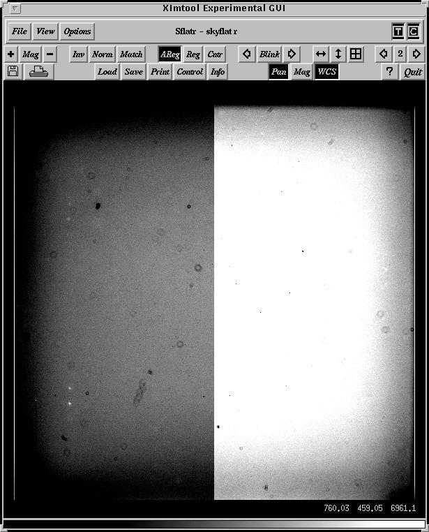
Here is an image of the dome flat divided by the sky flat across the full chip. The vignetting is also clear in this image.
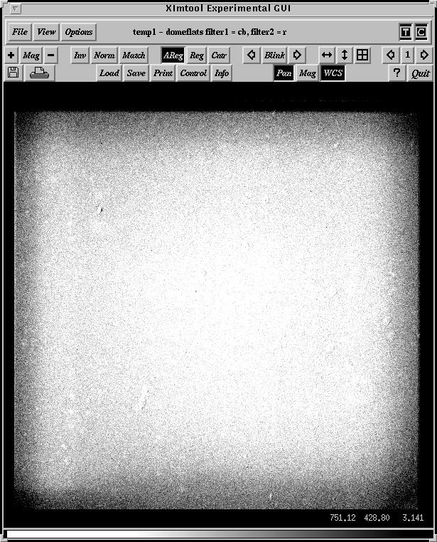
The "z" images showed fringing. Here is a typical z frame.
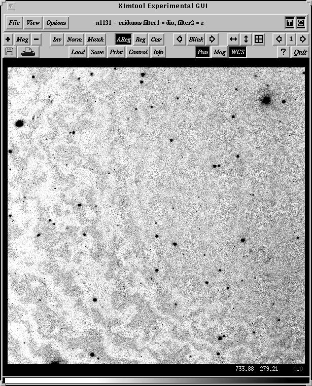
and here is the same image after defringing. The fringe frame was made by a simple median of all the long z exposures.
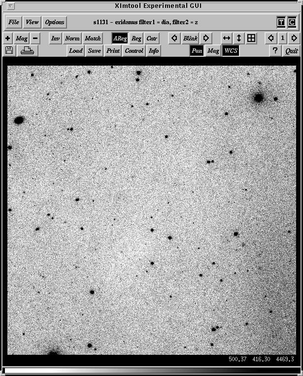
I averaged all the residuals for the 3 nights to look for trends. There were a few trends that are worrisome.
The next plot shows the residuals (O-C) of the Landolt standards. plotted against log10(counts). There is a small but real trend from 10**4 to 10*6 counts of about 0.015mag over this range.
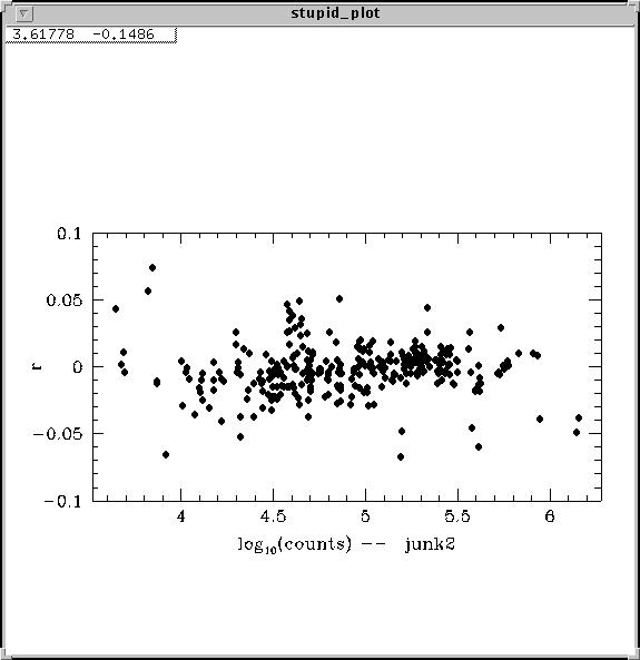
Doing the same plot against the library magnitude:
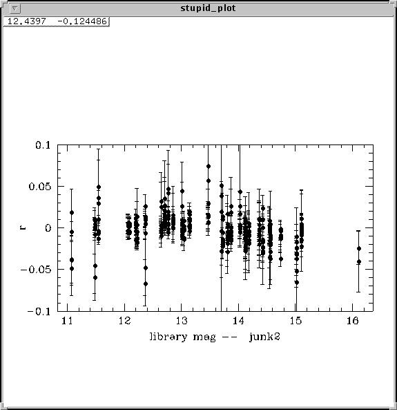
There was no obvious trend against x-direction, but in the y direction, one could see about a 0.02mag (full range) change in mag from the edge to center, in the sense that O was brighter than C:
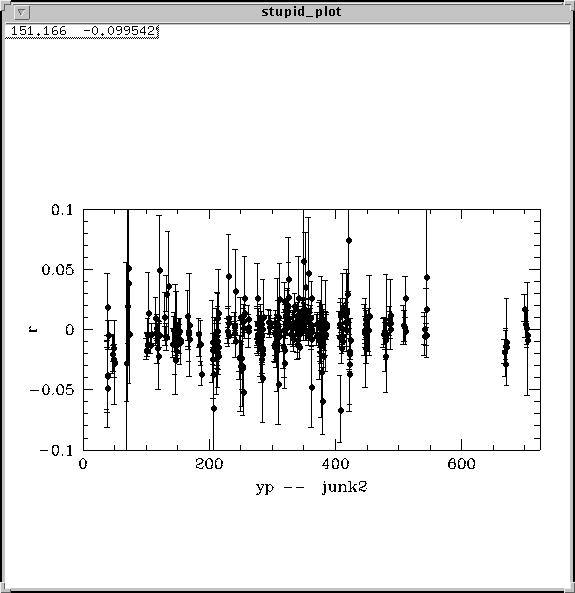
These data, remember, are the central 1500 pixels. Evidently there is still a small amount of vignetting.
At this point, I am not going to take out the effect, but it looks real.
New Stetson format for photometric reduction
NEW STUFF
We will run Stetson's new photometry programs. They are in /uw50/nick/daophot/newccd. I have them aliased as:
alias ccdnew $daophot/ccdnew
| alias | ndaomaster | $daophot/ccdnew/daomaster | |
| alias | ndaomatch | $daophot/ccdnew/daomatch | |
| alias | ndaogrow | $daophot/ccdnew/daogrow | |
| alias | ntrial | $daophot/ccdnew/trial | |
| alias | ncollect | $daophot/ccdnew/collect | |
| alias | nccdobs | $daophot/ccdnew/ccdobs | |
| alias | nccdlib | $daophot/ccdnew/ccdlib | |
| alias | nccdave | $daophot/ccdnew/ccdave | |
| alias | nccdstd | $daophot/ccdnew/ccdstd | |
| alias | nfetch | $daophot/ccdnew/fetch | |
| alias | njunk | $daophot/ccdnew/junk |
The advantage of these new programs is that one does not have to constantly re-edit the *.lib, *.tfm, files etc for subsets of the standard filters. Instead we can use files good for VBIRU photometry (Peter likes that order) for just BV photometry, or even just B photometry. The program inputs and outputs single magnitudes rather than V,B-V etc. That means you can just observe, say, B on a given night, and measure a color term for B in B-V (or whatever color). In addition, the programs have a space to include the telescope azimuth so we can more routinely check that the airmass is the same on either side of the meridian.
Of course, while you can solve for the color terms if you only observed in a single color, you can't calibrate new stars if you only have a single color.
Here is my first cut at a data reduction cookbook.
GENERAL REDUCTION NOTES for 0.9m f/13.5 data, 2048 format, Tek2K_3
| |---------------| | ||
| | | | ||
| E | | |t36 | |
| | | | ||
| |---------------| | ||
| N |
| |---------------| | |||
| | | | |||
| | |N | t60 f/7.5, 0.44"/pix | ||
| | | | |||
| |---------------| | |||
| E |
Data taken 13/14 Jun 2002. Reduced to [OTZF] in the usual fashion.
1. Load data from tape. I used a directory called:
20020613/opt/t36
Added this to loginuser.cl
#
set t20020613 = /uw52/nick/sn/sn02dj/20020613/opt/t36
and .daophot
#
setenv t20020613 /uw52/nick/sn/sn02dj/20020613/opt/t36
alias t20020613 "cd $t20020613"
2. Copy over setup files (including the *.opt,*.tfm files) from
copy /uw50/nick/daophot/optfiles/t36/* .
copy /uw50/nick/daophot/optfiles/t60/f75/* .
cl < setup
3. Create data directory to copy all unwanted data
mkdir data
cpimh *.fits del+
4. Run:
hedit *.imh OBSERVAT "CTIO" add+ up+ ver-
setjd *.imh
setairmass *.imh
azimuth *.imh calaz- flagit+ update+
The last commmand will add a KEYWORD called AZFLAG to be -1 W and +1 E for the hourangle. This will be used later for plotting the residuals. This is one of my IRAF commands in nickcl
We also make a file called mch.cl to stuff the MCHFILE information in the header and make inobj* files for the DAOMATCH stuff later. Here you make a file of the objects, blank separated, preferably with some filter other than U first.
task sed = $foreign
files obj*.imh | sed s/.imh// > in1
hsel @in1 $I,filters,title yes > in2
emacs in2 (blank separate the data, make sure first image is not U)
fields in2 1 > in3
To make the official version you must edit in the *.mch file. I will later make a program to do this automatically, but for right now, edit in a KEYWORD called MCHFILE with this information. If you have run prog59 above:
!$myprog/prog59 in3
cl < mch.cl
else:
hedit @inx MCHFILE obj069 add+ ver- update+ show+
5. Make the *.inf file
The new Stetson format has the *.mch file as the last field (which makes COLLECT easier to run) but it also means that you have to put the *.mch information into the *.inf file now. In addition, the *.inf file does not have the file title anymore, which is too bad.
We will make two versions of the *.inf file. The *.dat version is the old one which can be used for bookkeeping.
del junk.dat
hsel @in1 $I,filters,utmiddle,airmass,exptime,hjd,title,ha yes > junk.dat
!$myprog/prog3a junk.dat
0
t20020613
/uw50/nick/daophot/irafstuff/filters_t36new.dat
Now do:
del junk.dat
hsel @in1 $I,filters,utmiddle,airmass,azflag,exptime,hjd,mchfile yes >junk.dat
!$myprog/prog3b junk.dat
0
t20020613
/uw50/nick/daophot/irafstuff/filters_t36new.dat
or
del junk.dat
hsel @in1 $I,CCDFLTID,utmiddle,airmass,azflag,exptime,hjd,mchfile yes >junk.dat
!$myprog/prog3b junk.dat
0
!$myprog/prog3b junk.dat
0
t20020613
/uw50/nick/daophot/irafstuff/filters_t36new.dat
uyalo
/uw50/nick/daophot/irafstuff/filters_yalo.dat
You will now have a correct *.inf file.
/uw50/nick/daophot/irafstuff/filters_t36new.dat:
'dia v' 1
'dia b' 2
'dia i' 3
'dia r' 4
'dia u' 5
'dia z' 6
If you have to fix any headers, you must enter:
a. RA,DEC,epoch. You must enter the RA and DEC twice to get the right
notation.
b. hsel obj28*.imh $I,date-obs yes | translit - "-T" " " > junk1
c. filecalc junk1 "$2;$3;$4;$5-4" > junk2
d. astt files=junk2 obser=CTIO > junk3
and add the ST
e. Add an HA.
6. Subtract off the sky in I if needed.
I RECOMMEND COPYING ALL THE I SKIES FOR THE RUN INTO A DIRECTORY AND FORMING THE SKY FROM ALL THE IMAGES AT THE SAME TIME.
hsel @in1 $I,filters,exptime yes | sort col=3
emacs in4
ccdl @in4
irsky @in4 niter=10 sigma=2.5 irfltid="FILTER2" insuf="n" outsuf="s"
cl < sub.cl
starmask s????.imh up=75
addbpm @in4
imren s????.pl %s%n%*.pl
imdel s????.imh
imdel Skyi.imh
irsky @in4 usem+ rej- sig=2.5 niter=10 irfltid="FILTER2" insuf="n" outsuf="s"
subtract off DC of sky
fmed Skyi temp xwin=9 ywin=9
display Skyi 1 ; display temp 2
imdel Skyi ; imren temp Skyi
cl < sub.cl
imren @in4 data
imren *.pl data
imren s????.imh %s%n%*.imh
hedit @in4 bpm del+ ver-
DAOPHOT
Make sure you have the *.opt files. Make sure the daophot.opt file has the right gain and readnoise.
daophot.opt:
| Read noise | = | 1.4 | |
| Gain | = | 3.2 | |
| FWHM | = | 4.0 | |
| Fitting radius | = | 3.5 | |
| PSF radius | = | 15 | |
| Analytic model PSF | = | -3 | |
| Variable PSF | = | 1 | |
| Extra PSF cleaning passes | = | 5 | |
| High good datum | = | 45000 | |
| Watch progess | = | -2 | |
| Threshold | = | 7 |
allstar.opt:
| Fitting radius | = | 3.0 | |
| IS (Inner sky radius) | = | 2 | |
| OS (Outer sky radius) | = | 22 | |
| Redetermine Centroids | = | 10 |
photo.opt:
| A1 = | 4.0000 | |
| A2 = | 4.3506 | |
| A3 = | 4.8766 | |
| A4 = | 5.5779 | |
| A5 = | 6.4545 | |
| A6 = | 7.5065 | |
| A7 = | 8.7338 | |
| A8 = | 10.1364 | |
| A9 = | 11.7143 | |
| AA = | 13.4675 | |
| AB = | 15.3961 | |
| AC = | 17.5000 | |
| IS = | 17.5000 | |
| OS = | 25.0000 |
1. Measure the FWHM as:
del junk.dat
yaloshift @in1
etc.
2. Then run
!$myprog/prog39 junk.dat
This outputs fwhm.dat and fwhm1.dat. Use fwhm1.dat.
3. If you have standards, run BFIND2, using thresh about 6 for the bright stars.
For SN data, run BYALO. This will do BPASS2 and FINAL2. Use threshold of 5. For most f/13.5 data you can use a var = 1
If you use BPASS2 alone, edit the psf using:
!$myprog/prog11a r042 0.1
Lower the factor of 0.1 to about 0.07 for most frames.
Use dals for editing the psf stars. Often the center of a galaxy gets included in the psf.
If the SN or an important star was missed, run addals to add the object by hand.
Run FINAL2 to make the final psf phot and aperture files.
A note: DAOPHOT and all the programs identify stars by the x,y positions except in the case of making the psf. The psf is made from the file *.lst, and the stars here are identfied by the star name, not xy. If you change or add stars to the lst file, you must be sure that these names are the same as in the *.als files.
If you need to do ALLFRAME because the object is very weak, do:
a. make a *.mag file using DAOMASTER. Use 1 0.5 2 for input
b. renumber the *.mag stars using DAOPHOT
c. run BALLFRAME
d. run the following program to copy over the *.alf to *.als files
!$myprog/prog45 r055
e. make sure the *.mch file is pointing to the *.als data
f. run DAOMASTER to update the *.tfr file
!/uw50/nick/daophot/perl/daomaster.pl r032.mch
4. Make the *.lis file as
ls -1 *ap > t20020613.lis.
The *.lis file should have the same number of lines as the *.inf
file. You can check this as
wc *.lis *.inf
A note on file names. The following files should have the same name:
*.inf, *.lis, *.obs, *.tfm, *.clb. It also helps to call the directory by that name also. For instance, if there are 5 nights, the third night would be in directory n3, and the following files would be created in directory n3: n3.inf, n3.lis, n3.obs, n3.tfm and n3.clb.
At this point you may want to examine all the master images to see if there are any galaxies/double stars that will affect the growth curves.
Use in3 as a guide and run:
dals obj3333 suf=ap
5. Then run NDAOGROW. I used 3 unknowns. Last 2 are 0.9 and 0. I used 0.025mag error limits.
This produces *.tot files and a summary file *.gro. You can run "sm" at this point to see the growth curves. The command "see n3" will plot up 5 curves that represent the full range of seeing. The command "gro obj100" etc will plot the growth curves.
It is important to look at the curves quickly to see if they have appeared to converge.
In the new version of DAOGROW, the *.tot files have the sky in them.
If you need to rerun DAOGROW, run deldaogrow first.
To see the data:
rm -f junk ; sed 's/obj/gro obj/' in1 > junk
sm
see o20021109
It is important to check the data to see if DAOGROW has barfed on a frame with lots of saturated stars or galaxies.
6. Normally, one runs NDAOMATCH and NDAOMASTER to make the tables for each field.
This produces *.mch files for each field.
Peter's philosophy here is to have a directory with template images and *.tot files for the standards. You run NDAOMATCH starting with that file, and then feed in the program frames from the night in question. The *.mch file then has as a master image the template image. This works well provided that DAOMATCH runs flawlessly with all the program data.
I don't know if NDAOMATCH works better now. What I have done is to use yalocenter to make a junk file with shifts and run the following program. Put "als" or "tot" as needed.
yalocen inobjxxx
!$myprog/prog52b junk.dat als
This asks if you want to run daomaster. Do it.
!/uw50/nick/daophot/perl/daomaster.pl r032.mch
!ls -1 obj*.mch | wc
!ls -1 inobj* | wc
7. Display each first image in the *.mch files. Run the iraf task "fetch" and then the fortran task "fetch" to make the *.fet files.
The IRAF fetch inputs either an "a" key or an "x" key. Use the "a" key if the object looks like it can be centered. If the object is near a bad pix, use the "x" key.
NOTE THAT THERE IS A NEW VERSION OF FETCH. I NEED TO MODIFY IT TO WORK IN THE IRAF TASK.
You can get the new Stetson fields at:
http://cadcwww.hia.nrc.ca/cadcbin/wdbi.cgi/astrocat/stetson/query [5]
Get the *.fits.gz, *.pos, *.pho files.
Run prog2 in /uw52/nick/stetson to make a *.tot file with the brighter stars.
prog2 NGC2437
displ NGC2437.fits
tvm 1 NGC2437.xy label+ mark=point points=5 color=202 tx=2 ny=-6 nx=10
To add stars into the *.lib file, use
~/daophot/library/prog12
PG2213.pho
To display the new stars and to cull only the bright ones:
prog2 NGC2437
displ NGC2437.fits
tvm 1 NGC2437.xy label+ mark=point points=5 color=202 tx=2 ny=-6 nx=10
If the STetson field is too big, run:
/uw52/nick/stetson/prog4
to clip the field.
If the standard fields cover a larger area than a single image, use MONTAGE2 on the *.mch file. This makes an image obj120m. The offsets (needed for FETCH) are sent to offset.dat
~/daophot/perl/montage2.pl obj120
For some of the Stetson fields, there are way too many stars to id. I would prefer some sort of id based on WCS, but here is a quick solution.
a. Copy over the *.tot file, such as Ru149.tot
!cp /uw52/nick/stetson/L95_100.tot .
!cp /uw52/nick/stetson/Ru149.tot .
!cp /uw52/nick/stetson/PG1323s.tot .
!cp /uw52/nick/stetson/PG0918.tot .
!cp /uw52/nick/stetson/PG1047.tot .
!cp /uw52/nick/stetson/L104.tot .
b. Run NDAOMATCH on Ru149.tot and obj1114.tot where the latter is the master image in the *.mch file.
x(1) = 2316.8152 + -0.0015 x(2) + -0.8646 y(2)
y(1) = 1110.2642 + 0.8646 x(2) + -0.0015 y(2)
c. Run
!/uw50/nick/daophot/perl/daomaster.pl L95_100
!/uw50/nick/daophot/perl/daomaster.pl Ru149
!/uw50/nick/daophot/perl/daomaster.pl PG1323s
!/uw50/nick/daophot/perl/daomaster.pl PG0918
!/uw50/nick/daophot/perl/daomaster.pl PG1047
to output a *.tfr file.
d. Run
!/uw52/nick/stetson/prog3 L95_100
!/uw52/nick/stetson/prog3 Ru149
!/uw52/nick/stetson/prog3 PG1323s
!/uw52/nick/stetson/prog3 PG0918
!/uw52/nick/stetson/prog3 PG1047
This will output the correct *.fet file for the master image. Believe me.
8. Now, if you are doing standards, enter the data into NCOLLECT.
This runs much more easily than in the past.
nick% ncollect
Name of output photometry file: t20020613
Creating new file.
| Label for magnitude 1: | v | |
| Label for magnitude 2: | b | |
| Label for magnitude 3: | i | |
| Label for magnitude 4: | r | |
| Label for magnitude 5: | u | |
| Label for magnitude 6: | ||
| New output file name (default OVERWRITE): | ||
| File with exposure information (default NONE): | t20020613 | |
| Typical FWHM, maximum radius: | 2 10 | |
| Photometry-filename prefix: | ||
| ==> Enter NONE if there are no psf files. <== | ||
| Default filename extension (default als): | NONE | |
| Input .TOT file: |
9. Now you run NCCDSTD to get the transformations.
This new program inputs a *.lib and *.obs file which have the same magnitude order.
head landolt.lib
| 5 FILTERS: | V | B | I | R | U | ||||||||
| tphe-a | 14.651 | 0.0066 | 15.444 | 0.0087 | 13.810 | 0.0071 | 14.216 | 0.0066 | 15.824 | 0.0121 | 29 | 12 | l92.dat |
| tphe-b | 12.334 | 0.0158 | 12.739 | 0.0158 | 11.799 | 0.0158 | 12.072 | 0.0158 | 12.895 | 0.0071 | 29 | 17 | l92.dat |
head t20020613.obs
| 5 MAGNITUDES: | (1) v | (2) b | (3) i | (4) r | (5) u | ||||||||
| 4 42 Midnight | |||||||||||||
| Star | Fil | H | M | X | Az | Int | Mag | sigma | corr | x | y | sky | |
| pg1047 | 2 | 23 | 45 | 1.274 | -1.0 | 19.000 | 13.301 | 0.0036 | -0.027 | 1252.45 | 1079.36 | 3.052 | obj069 |
| Pg1047a | 2 | 23 | 45 | 1.274 | -1.0 | 19.000 | 14.422 | 0.0061 | -0.047 | 1147.02 | 1165.27 | 2.901 | obj069 |
This produces *.rsd files which you can plot with sm. Use "resids highz99r" and "resids highz99i" which inputs the data. There is a macro called rsd.macro that you copied over. Run SM and input:
sm
: macro read rsd.macro
etc
This macro plots up the data. Look especially carefully at the UT and X plots to look for trends. Add a "T" term to the solution if needed.
To see all the resids, do:
grep obj o20021204.rsd > junk.rsd
and plot
A quick way to find bad stars is to do:
grep o20030131.rsd -e \? -e # | sort +19
10. Run NCCDAVE to output the *.net and *.ave file.
Note that this program will output the specified number of filters in the *.obs file. Again, you can input the VBIRU *.lib file, and the reduced number of filters *.obs file to get out the *.net file.
11. Run NTRIAL to get the final reduced psf photometry.
You have to have a fresh copy of the *.tfr file by running daomaster.pl. The pairs file can be used to search for variables. NTRIAL uses the *.mch file to determine what data to input.
nick% ntrial
| Transfer file: | obj074 |
| Library file (default obj074.lib): | t20020613.net |
| Information file (default obj074.inf): | t20020613 |
| Pair file (default obj074.prs): | END-OF-FILE |
| FETCH file (default obj074.fet): | |
| Critical radius: | 8 |
| Output file name (default obj074.fnl): |
See below for variable star searches
SMALLER NUMBER OF FILTERS THAN VBIRU
If you have a smaller number of filters than VBIRU, do the following.
1. Make sure the *.obs file has only the filters you want to reduce.
For instance, if you want VB but you also have I in the *.obs file, remove the I data. The NCCDSTD program will attempt to reduce all the filters in the *.obs file.
2. Edit the *.tfm file to include only the filters of interest.
For instance, I used the following *.tfm file for VI reductions, but
inputting the VBIRU *.lib file. Note I had to change the color of O1 (V) from I2 to I3 because I have removed all the B information from the *.obs file.
I1 = M1
#I2 = M2-M1
I3 = M1-M3
#I4 = M1-M4
#I5 = M5-M2
O1 = M1 + A0 + A1*I3 + A2*X
#O2 = M2 + B0 + B1*I2 + B2*X
O3 = M3 + C0 + C1*I3 + C2*X
#O4 = M4 + D0 + D1*I4 + D2*X
#O5 = M5 + E0 + E1*I5 + E2*X
By doing this, NCCDSTD will run on only the VI data. NCCDAVE will only output the VI data. Very simple to use!
For NTRIAL, you can use the full *.inf, *.net, and *.clb file (VBIRU) even for the subset of filters. It is the *.mch file that limits the input data. NTRIAL is quite intelligent. For instance, I input the VI data in *.mch file. The *.clb file had the I color term as V-I and the V color term as B-V. The output *.fnl file had the I data correct, but no V data because it lacked the B filter for the color term. But the program still ran.
VARIABLE STAR SEARCH
If you want, you can use trial to search for variable stars.
You can input a file called *.prs to search for variable stars. You must have a file with pairs of observations where you don't think that the star varied between observations (like CR SPLITS in HST). The program will output lots of cool statistics files and also attempt a period analysis if it finds a variable.
To make a variable star search, set up a .prs file for SN1987A:
grep -h SN1987A *.inf | sort +7n > SN1987A.prs
This sorts on JD and does not put the annoying "sort" header crap in the output.
Then just go through the file putting blank lines between the pairs you want.
For this to work most efficiently, it is best to have all your various .inf files stored in the same location. Me, I have a directory named `save' where I keep all the master .mch, .mag, .inf files for fields that span many observing runs, and I have a directory for each observing run.
TO USE: Run the program once with
Limits on Variability, weight, period, magnitude: 9999, 9999, 9999, 0
| "Variability" | is the minimum value of the variability index. More later. |
| "Weight": | if a star appears in both images of an image pair which you have specified, that pair of observations is given weight one. If you have specified that a single image is to be considered by itself OR if the star appears in only one image of a pair, that observation is paired with itself and given weight one-half. |
| "Period": | later when I have the period-finding algorithm robust and reliable, once a candidate variable has been detected, the software will search for the best light curve considering all periods from the time difference between the first and last observation down to some minimum period that you specify. |
| "Magnitude:" | The software will not consider variability in any star fainter than some magnitude limit you specify, assuming that observations of faint stars are inherently flaky. |
It doesn't actually find any variables with these parameters, but it will put values of all the relevant indices into the output file. Use
supermongo or IDL or whatever to plot variability index vs magnitude, variability index vs weight, weight vs magnitude, and decide what
limits you believe in. Then run the program again specifying the
MINIMUM VARIABILITY INDEX, MINIMUM WEIGHT, 9999, MAGNITUDE LIMIT.
For each star with VARIABILITY INDEX > MINIMUM, WEIGHT > MINIMUM, and MAGNITUDE < MAXIMUM it will produce a file giving magnitude, sigma, filter ID and HJD for every observation of that star, but since you have set PERIOD = 9999 (or whatever) it will not actually try to derive a period and light curve (since that part of the software isn't trustworthy yet). Instead, you can feed those output files to whatever algorithm you favor.
A typical output is:
example of *.fnl output. I have clipped out the BIRU, chi, and sharp cols
| WSI | KUR | VAR | WEI | |||||||||||
| 5 FILTERS: | V | |<---------vary----------> | | | |||||||||||
| 200084 | 2053.907 | 1306.190 | 15.044 | 0.0117 | -0.974 | 0.000 | 0.000 | 1.5 | 2 | 1 | 1 | 1 | 1 | |
| 141 | 1299.840 | 1307.058 | 16.615 | 0.0037 | -0.367 | 0.955 | -0.440 | 7.0 | 6 | 2 | 2 | 2 | 2 | |
| 142 | 563.164 | 1315.237 | 17.511 | 0.0054 | -0.762 | 0.991 | -0.947 | 6.5 | 6 | 2 | 2 | 2 | 1 | |
| 200086 | 189.653 | 1330.617 | 20.153 | 0.0542 | -1.086 | 0.964 | -1.313 | 2.5 | 3 | 0 | 2 | 2 | 0 | |
| 143 | 509.466 | 1332.737 | 15.832 | 0.0026 | -0.332 | 0.989 | -0.411 | 7.0 | 6 | 2 | 2 | 2 | 2 | |
| 200087 | 431.215 | 1335.806 | 20.487 | 0.0708 | -0.332 | 0.000 | 0.000 | 0.0 | 1 | 0 | 2 | 2 | 0 | |
| 200088 | 1025.079 | 1342.062 | 19.567 | 0.0776 | -0.332 | 0.000 | 0.000 | 0.0 | 2 | 0 | 1 | 1 | 0 | |
| 144 | 1480.070 | 1355.231 | 19.503 | 0.0197 | -1.076 | 0.993 | -1.339 | 6.0 | 6 | 2 | 2 | 2 | 0 | |
| 200089 | 563.927 | 1363.607 | 20.371 | 0.0683 | -1.076 | 0.000 | 0.000 | 0.0 | 1 | 0 | 2 | 2 | 0 | |
| 200090 | 1351.710 | 1374.867 | 20.336 | 0.0406 | -1.076 | 0.000 | 0.000 | 0.0 | 2 | 0 | 2 | 2 | 0 | |
| 145 | 1734.359 | 1376.684 | 18.357 | 0.0145 | 0.022 | 0.989 | 0.027 | 6.0 | 6 | 2 | 2 | 2 | 0 | |
| 200091 | 334.059 | 1391.754 | 19.730 | 0.0187 | -0.432 | 0.984 | -0.533 | 4.5 | 5 | 0 | 2 | 2 | 0 | |
| 200094 | 1117.611 | 1413.930 | 19.628 | 0.0483 | -0.049 | 0.995 | -0.062 | 2.0 | 3 | 0 | 1 | 2 | 0 | |
WSI is the Welch/Stetson variability index. See Welch & Stetson 1993, AJ, 105, 1813. A large positive number is a variable. Non-variable
stars should scatter around 0.
WEI is described above. In this case, I had 7 frame pairs.
VAR = 1.2533*KUR*WSI. I am not clear as to the meaning of VAR.
D
1 May 2001
The MagIC is the MIT fast read camera at the Baade telescope. The scale is 0.069"/pix. There is no manual yet.
The raw read format is [2064,2062][ushort]
Estimated gain:
| <> | sig | med | N | ||||
| ll: | |||||||
| 1.974 | 0.106 | 1.974 | 37 | (e-/ADU) | gain | ||
| 15.225 | 1.300 | 15.221 | 37 | (e-) | ron | ||
| lr: | |||||||
| 2.019 | 0.109 | 2.021 | 32 | ||||
| 13.066 | 1.357 | 12.753 | 32 | ||||
| ul: | |||||||
| 2.065 | 0.121 | 2.067 | 34 | ||||
| 12.476 | 1.271 | 12.490 | 34 | ||||
| ur: | |||||||
| 1.890 | 0.125 | 1.881 | 31 | ||||
| 12.562 | 1.305 | 12.822 | 31 |
So a value of 2.0 and 13.5 is fine.
Saturation is about 45000.
| 2.36' | |
| |--------|-------| | |
| | | | |
| E | | | |
| | | | |
| |--------|-------| | |
| N |
CCD REDUCTIONS
This is a quick guess at what to do.
An implot shows the following structure:
x:
1:4 bad
5:1026 good data
1027:1032 bias (exclude 1027 which is slightly high)
1033:1038 bias (exclude 1038 which is slightly high)
1039:2060 good data
2061:2064 bad
y:
1 bad
2:1025 good
1026:1038 bias region (?)
1039:2061 good
2062 bad
I am not sure where there is a "bias" here. I will assume it is in the "x" direction, but will have to check on this.
Rename the images. IRAF does not like names with start with "01" like 010317.010.fits, because it will tranlate it into octal. You have to refer to the data as "010317.010.fits" within IRAF. I changed the names to q*.imh
rename
cpimh *.imh del+
hedit r*.imh observat "lco" up+ ver-
setjd *.imh hjd=""
I wrote a task which pulls apart the 4 quads, reduces them to [OT] and reassembles the image.
To run it, do the following:
1. Set up a special uparm as:
setup:
set stdimage = imt2048
set uparm = /uw50/nick/uparm/magic/
noao
ctio
nickcl
imred
ccdred
keep
Now edit ccdr:
ccdr:
| pixeltype = | "real real") | Output and calculation pixel datatupes |
| (verbose = | yes) | Print log information to the standard output? |
| (logfile = | "logfile") | text log file |
| (plotfile = | "") | Log metacode plot file |
| (backup = | "") | Backup directory or prefix |
| (instrument = | "myiraf$/magic.dat") | CCD instrument file |
| (ssfile = | "myiraf$/magic.sub") | Subset translation file |
| (graphics = | "stdgraph") | Insteractive graphics output |
| (cursor = | "") | Graphics cursor input |
| (version = | "2: October 1987") | |
| (mode = | "ql") | |
| ($nargs = | 0) |
ccdpr:
| images = | "" | List od CCD images to correct |
| (output = | "") | List of output CCD images |
| (ccdtype = | "") | CCD image type to correct |
| (max_cache = | 0) | Maximun image caching memory (in Mbytes) |
| (noproc = | no) | List processing steps only?\n |
| (fixpix = | no) | Fix bad CCD lines and columns? |
| (overscan = | no) | Apply overscan strip correction? |
| (trim = | no) | Trim the image? |
| (zerocor = | no) | Apply zero level correction? |
| (darkcor = | no) | Apply dark count correction? |
| (flatcor = | no) | Apply flat field correction? |
| (illumcor = | no) | Apply illumination correction? |
| (fringecor = | no) | Apply fringe correction? |
| (readcor = | no) | Convert zero level image readout correction? |
| (scancor = | no) | Convert flat fiel image to scan correction?\n |
| (readaxis = | "line") | Read out axis (column|line) |
| (fixfile = | "") | File describing the bad lines and columns |
| (biassec = | "") | Overscan strip image section |
| (trimsec = | "") | Trim data section |
| (zero = | "") | Zero level calibration image |
| (dark = | "") | Dark count calibration image |
| (flat = | "") | Flat field images |
| (illum = | "") | Illumination correction images |
| (fringe = | "") | Fringe correction images |
| (minreplace = | 1.) | Minimum flat field value |
| (scantype = | "shortscan") | Scan type (shortscan|longscan) |
| (nscan = | 1) | Number of short scan lines\n |
| (interactive = | yes) | Fit overscan interactively? |
| (function = | "leg") | Fitting function |
| (order = | 1) | Number of polynomial terms of spline pieces |
| (sample = | "*") | Sample points to fit |
| (naverage = | 1) | Number of sample points to combine |
| (niterate = | 1) | Number of rejection iterations |
| (low_reject = | 3.) | Low sigma rejection factor |
| (high_reject = | 3.) | High sigma rejection factor |
| (grow = | 0.) | Rejection growing radius |
| (mode = | "ql") |
magic.dat:
| subset | filtert | |||
| exptime | exptime | |||
| darktime | darktime | |||
| imagetyp | imagetyp | |||
| biassec | biassec | |||
| datasec | datasec | |||
| trmsec | trimsec | |||
| fixfile | fixfile | |||
| FOCUS | ||||
| OBJECT | object | |||
| DARK | zero | #Old software | ||
| FLAT | flat | |||
| BIAS | zero |
magic.sub
| 'MagIC_t0' | opaque | |
| 'MagIC_B' | B | |
| 'V_LC3014' | V |
ccdmagic:
| images = | "q*.imh" | input images |
| (bias1 = | "[1028:1032,2:1025]") | bias for ll amp |
| (bias2 = | "[1033:1037,2:1025]") | bias for lr amp |
| (bias3 = | "[1028:1032,1039:2061]") | bias for ul amp |
| (bias4 = | "[1033:1037,1039:2061]") | bias for ur amp |
| (trim1 = | "[5:1026,2:1025]") | trim for ll amp |
| (trim2 = | "[1039:2060,2:1025]") | trim for lr amp |
| (trim3 = | "[5:1026,1039:2061]") | trim for ul amp |
| (trim4 = | "[1039:2060,1039:2061]") | trim for ur amp |
| (prefix = | "r") | Prefix for reduced data |
| (niter = | 3) | Number of iterations for bias |
| (reject = | 2.5) | Low and high sigma rejection |
| (imglist = | "tmp$tmp15763ka") | |
| (mode = | "ql") |
Combine the biases as:
zerocomb @inbias out=Zero
Combine the flats:
flatcomb @inb
flatcomb @inv
Now process the data as:
ccdpr r*.imh
(note: I forgot to change the IMAGETYP on some of the "focus" frames that were labeled "FLAT" to "OBJECT". For some reason, the ccdmagic processing clipped the data at 0 with no negative values. I can't figure out why it did this, but make sure that IMAGETYP is set correctly before doing ccdmagic and ccdpr)
EDIT IN THE AIRMASS
hedit ra,dec,epoch into the header.
To do this, you must enter the value twice (an IRAF bug) or use my script editcoord:
editcoord @in10 "07:24:15" "-00:32:55" 2000.
editcoord @in11 "11:01:36.4" "-06:06:32" 2000.
editcoord @in12 "10:50:03" "-00:00:32" 2000.
etc.
Now calculate the ST. I will write an IRAF task to do this later.
hsel d*.imh $I,date-obs,ut yes > junk
trans junk "-" " " | trans STDIN '"' " " > junk1
filecalc junk1 "$2; $3; $4; $5-4" form="%3d%3d%3d\t%h13" > junk2
junk2 should have:
yyyy mm dd LT
where LT is local time (!). You had better check that this is correct!
Then run
asttimes files=junk2 observatory=lco
This outputs a text file with the ST. Edit this file to input the ST into the header.
hedit r*.imh $I,st yes
(you have to run this twice to get the proper units)
Calculate the airmass:
setairmass @in1 observatory=lco
Put in the hour angle.
hedit @in1 ha '(st-ra)' add+
DAOPHOT (the following is pretty specific to my reduction programs)
copy the *.opt files, *.lib, *.tfm
Make the *.inf file
hsel @in1 $I,filtert,ut,airmass,exptime,jd,title,ha yes > junk1.dat
translit junk1.dat '"' ' ' > junk.dat
!$myprog/prog3a junk.dat
/uw50/nick/daophot/irafstuff/filters_magic.dat
2. Measure the FWHM as:
del junk.dat
yaloshift @in1
etc.
Then run
$myprog/prog39 junk.dat
3. For standards, run BFIND2,using thresh about 12 for the bright stars.
4. DAOGROW
ls -1 *.ap > magic.lis
Use 3 unknowns, 0.9 0 for the last two, and set the uncertainty to 0.02.
5. DAOMATCH, DAOMASTER
Use DAOMATCH or run yalocen on the data followed by.
$myprog/prog52a junk.dat
head -1 temp.mch
mv temp.mch xxx.mch
or
sed s/tot/als/ temp.mch > rxxx.mch
For then input to DAOMASTER use:
ty myiraf$/in4_yaloopt
7. Display each first image in the *.mch files.
Run the iraf task "fetch" and then the fortran task "fetch" to make the *.fet files.
8. Enter the data into COLLECT. Use prog43 to speed things up.
!$myprog/prog43 ccd12.mch
COLOR TERMS
The BV color solution for this night was based on 27 standards, of two fields (Ru149 and pg1047) taken at the same airmass but 4 hours apart. The night looked quite photometric.
M1=I1+I2
M2=I1
I1=M2
I2=M1-M2
O1 = M1 + A0 + A1*I2 + A2*X + A3*T
O2 = M2 + B0 + B1*I2 + B2*X + B3*T
A2=0.24
A3=0. m:b,v, I:V,B-V
B2=0.12
B3=0.
A0 = -1.1355085 0.0061041 <<
A1 = -0.0297454 0.0108595 <<
B0 = -1.4578034 0.0057458 <<
B1 = 0.0581488 0.0096709 <<
S1 = 0.0177567 <<
S2 = 0.0197406 <<
So:
b = B + -0.030*(B-V) + zp
v = V + +0.058*(B-V) + zp
The V term is a bit higher than usual.
The range in color was (-0.11,1.12). The color terms were not very linear and the fits were not very good, even though the data are extremely photometric. That is why the residuals had an extra scatter (S1,S2) of 0.017 and 0.019mag. The color term may be quadradic. For a
photometric night on smaller telescopes, these are 0. There may be a small photometric gradient in x of about 0.04mag. Without more standards, I can't say.
mag at 1ADU/s
B 26.17
V 26.42
Data from 3 Oct 2000
In the first two weeks of Sept 2000, Darren has fixed the optical channel. It now reads out in full 2048 mode. See:
http://www.astronomy.ohio-state.edu/YALO/news.html [6]
Some changes:
gain = 3.6 electrons/ADU
readout noise = 11 electrons (rms)
saturation (full well) is at about 85000e- or 24000ADU for this gain.
| In Oct 2000, I measured: | ||||
| biwgt | sig | med | N | |
| 3.510 | 0.234 | 3.538 | 69 | |
| 10.542 | 0.877 | 10.633 | 69 | |
| In March 2001, | ||||
| 3.526 | 0.233 | 3.538 | 148 | |
| 11.284 | 1.195 | 11.335 | 148 |
In April 2002, I find:
| right amp | left amp | |||||||
| 3.472 | 0.168 | 3.460 | 78 | 3.481 | 0.276 | 3.495 | 78 | |
| 16.720 | 2.109 | 16.312 | 78 | 15.301 | 1.251 | 15.408 | 76 | |
I measured (1529,1021)ccd=(512,512)ir The scale between the CCD and IR is 1.338 (roughly), implying the optical scale is 0.298"/pix.
The format is now read out as [1:2144,1:2048]. The actual format is strange. There are 32 pixels of bias, followed by 16 of "hardware
underscan" followed by 1024 pixels in the serial direction. Thus:
| Darren's numbers | ||
| BIASSEC1 | [1:32,1:2048] | |
| hardware overscan | [33:48,1:2048] | |
| DATASEC1 | [49:1072,1:2048] | |
| DATASEC2 | [1073:2097,1:2048] | |
| hardware overscan | [2098:2112,1:2048] | |
| BIASSEC2 | [2113:2144,1:2048] | |
| TRIMSEC | [49:2096,1:2048] |
I think these are slightly wrong, because the DATASEC2 is 1025 pixels and the hardware overscan is 15. I have changed these slightly to give a 2048:2048 readout. I have also modified the biassec values slightly because there is DC rolloff. My numbers:
string bias1 {"[8:32,1:2048]", prompt='bias for left amp'}
string bias2 {"[2113:2142,1:2048]", prompt='bias for right amp'}
string trim1 {"[49:1072,1:2048]", prompt='trim for left amp'}
string trim2 {"[1073:2096,1:2048]", prompt='trim for right amp'}
string trim {"[49:2096,1:2048]", prompt='Header info for trim'}
I have written a task called "ccdyalo" task ccdyalo = home$scripts/ccdyalo.cl
which will tear apart the CCD image in two, do the overscan and trim and join them back into one image as [OT]. After that, you must finish the processing with ccdpr, turning on [ZF]
In Feb 2001, the images were [2152:2048]. Someone had changed the overscan from 32 to 36pix. There is a fits keyword which gives this - OVERSCNX. It always should be 32. If it is 36, use:
lpar ccdyalo
| images = | "ccd010306.00??.imh" | input images |
| (bias1 = | "[8:32,1:2048]") | bias for left amp |
| (bias2 = | "[2121:2150,1:2048]") | bias for right amp |
| (trim1 = | "[53:1076,1:2048]") | trim for left amp |
| (trim2 = | "[1077:2100,1:2048]") | trim for right amp |
| (trim = | "[53:2100,1:2048]") | Header info for trim |
| (trim4 = | "[1039:2060,1039:2061]") | trim for ur amp |
| (prefix = | "r") | Prefix for reduced data |
| (niter = | 3) | Number of iterations for bias |
| (reject = | 2.5) | Low and high sigma rejection |
| (imglist = | "tmp$tmp15262gb") | |
| (mode = | "ql") |
DATA REDUCTION:
-3. You will be using a package I defined: nickcl. To use this easily put in the "login.cl" (not loginuser.cl) the following:
reset nickcl = /uw50/nick/nickcl/
task nickcl.pkg = "nickcl$nickcl.cl"
-2. Make sure you have aliases setup for the data:
We will use a directory structure as:
We will use a directory structure as:
| /uw54/nick/sn/sn01cn | |||||
| | | |||||
| | | |||||
| 20010630 | |||||
| | | |||||
| ------------------------------------------------ | |||||
| | | | | ||||
| | | | | ||||
| opt | ir | ||||
.daophot
# sn99em
setenv i20010630 /uw54/nick/sn/sn01cn/20010630/ir
alias i20010630 "cd $i20010630"
setenv o20010630 /uw54/nick/sn/sn01cn/20010630/opt
alias o20010630 "cd $o20010630"
You can also set them up for IRAF as:
loginuser.cl:
set o20010630 = /uw54/nick/sn/sn01cn/20010630/opt/
set i20010630 = /uw54/nick/sn/sn01cn/20010630/ir/
1. Make a setup file that points to a unique uparm:
copy /uw50/nick/daophot/optfiles/yalo/opt/setup .
setup:
set stdimage = imt2048
set uparm = /uw50/nick/uparm/yaloccd/
noao
ctio
nickcl
imred
digi
apphot
astu
ccdred
ccdred.instrument = "myiraf$yalo_ccd.dat"
ccdred.ssfile = "myiraf$yalo_ccd.sub"
loadit.format = "2048"
loadit.statsec = "700:800,700:800"
keep
Run:
cl < setup
2. Change to imh
cpimh *.fits del+
3. Fix the header and add the JD and AIRMASS correctly.
You can run "yalohead" to do the addition of epoch, ctio, and jd-old. It also runs setjd and setairmass.
yalohead ccd*.imh
If you need to run setjd or setairmass:
files ccd*.imh > in1
setjd @in1 date="UTDATE" time="UT" exposure="EXPTIME" epoch="EQUINOX"
setairmass @in1
The secz and airmass should be about the same, or something is wrong:
hsel r*.imh $I,airmass,secz yes
setjd @in1 date="UTDATE" time="UT" exposure="EXPTIME" epoch="EQUINOX"
4. Run ccdyalo on all the data.
This will make [OT] images called rccd*.imh. Make sure the raw images are format [2144,2048], or ccdyalo will not work correctly.
ccdyalo ccd*.imh
5. There are lots of wild pixels. Run:
imrep rccd*.flat?.imh value=65535 lower=65535 upper=INDEF
imrep rccd*.flat?.imh value=0 lower=INDEF upper=-100
5.5 If there are U twilight skies, you must combine these using "flatcomb"
flatcomb rccd011217skyu*.imh
imren FlatU rccd011217.flatu.imh
6. Now run ccdpr on the data. Run ccdlist first to see if the filters and imagetyp are correct.
ccdl rccd*.imh
Then a dry run:
ccdpr rccd*.imh nop+
Then
ccdpr rccd*.imh
| images = | "rccd*.imh" | List od CCD images to correct |
| (output = | "") | List of output CCD images |
| (ccdtype = | "") | CCD image type to correct |
| (max_cache = | 0) | Maximun image caching memory (in Mbytes) |
| (noproc = | no) | List processing steps only?\n |
| (fixpix = | no) | Fix bad CCD lines and columns? |
| (overscan = | no) | Apply overscan strip correction? |
| (trim = | no) | Trim the image? |
| (zerocor = | yes) | Apply zero level correction? |
| (darkcor = | no) | Apply dark count correction? |
| (flatcor = | yes) | Apply flat field correction? |
| (illumcor = | no) | Apply illumination correction? |
| (fringecor = | no) | Apply fringe correction? |
| (readcor = | no) | Convert zero level image readout correction? |
| (scancor = | no) | Convert flat fiel image to scan correction?\n |
| (readaxis = | "line") | Read out axis (column|line) |
| (fixfile = | "") | File describing the bad lines and columns |
| (biassec = | "") | Overscan strip image section |
| (trimsec = | "") | Trim data section |
| (zero = | "rccd*.bias") | Zero level calibration image |
| (dark = | "") | Dark count calibration image |
| (flat = | "rccd*.flat?.imh") | Flat field images |
| (illum = | "") | Illumination correction images |
| (fringe = | "") | Fringe correction images |
| (minreplace = | 1.) | Minimum flat field value |
| (scantype = | "shortscan") | Scan type (shortscan|longscan) |
| (nscan = | 1) | Number of short scan lines\n |
| (interactive = | yes) | Fit overscan interactively? |
| (function = | "median") | Fitting function |
| (order = | 8) | Number of polynomial terms of spline pieces |
| (sample = | "*") | Sample points to fit |
| (naverage = | 1) | Number of sample points to combine |
| (niterate = | 3) | Number of rejection iterations |
| (low_reject = | 2.5) | Low sigma rejection factor |
| (high_reject = | 2.5) | High sigma rejection factor |
| (grow = | 0.) | Rejection growing radius |
| (mode = | "ql") |
The data are now reduced to [OTZF].
7. To create the *.inf file. First I like to make the names shorter, because I have fat fingers.
imren rccd010630.0*.imh %rccd010630.0%r%*.imh (or whatever)
del in*
del junk*
files r???.imh > in1
hsel @in1 $I,CCDFLTID,utmiddle,airmass,exptime,hjd,title,ha yes > junk.dat
!$myprog/prog3a junk.dat
use:
/uw50/nick/daophot/irafstuff/filters_yalo.dat
8. You can run fixpix on the data, if you want to make pretty images.
Dont do this on the data you will use to measure photometry.
fixpix r???.imh mask=mask.pl
9. Divide by the mask image (see below if you don't have a mask image).
You only need to make a mask every few weeks or so. Don't waste your time doing lots of masks! If the mask image has good=0, bad=1, you must first do:
imar r???.imh / maskdao r???.imh divzero=65535
MAKING THE MASK
To avoid confusion with the badpixels, I am going to reduce these data always into 2048:2048, and merely mask off the bad pixels.
badpix:
# badpix for reduced data format YALO CCD [2048,2048]
#BIASSEC1 [8:32,1:2048]
#BIASSEC2 [2113:2142,1:2048]
#DATASEC1 [49:1072,1:2048]
#DATASEC2 [1073:2096,1:2048]
#TRIMSEC [49:2096,1:2048]
# oct 2000 nbs
| 207 | 207 | 758 | 2048 | |
| 303 | 312 | 1600 | 2048 | |
| 970 | 970 | 1116 | 2048 | |
| 976 | 977 | 1428 | 2048 | |
| 1168 | 1168 | 1822 | 2048 | |
| 1564 | 1567 | 1901 | 2048 | |
| 1594 | 1595 | 1 | 2048 | |
| 1606 | 1606 | 1 | 2048 | |
| 1610 | 1610 | 1 | 2048 | |
| 1661 | 1662 | 810 | 2048 | |
| 1686 | 1686 | 148 | 2048 | |
| 1689 | 1690 | 1200 | 2048 | |
| 1875 | 1876 | 857 | 2048 | |
| 1908 | 1908 | 1658 | 2048 | |
| 1955 | 1956 | 1865 | 2048 | |
| 1962 | 1964 | 573 | 2048 | |
| 1972 | 1972 | 725 | 2048 |
badpix1:
# badpix for raw data format YALO CCD [2144,2048]
#BIASSEC1 [8:32,1:2048]
#BIASSEC2 [2113:2142,1:2048]
#DATASEC1 [49:1072,1:2048]
#DATASEC2 [1073:2096,1:2048]
#TRIMSEC [49:2096,1:2048]
# oct 2000 nbs
| 255 | 255 | 758 | 2048 | |
| 351 | 360 | 1600 | 2048 | |
| 1018 | 1018 | 1116 | 2048 | |
| 1024 | 1025 | 1428 | 2048 | |
| 1216 | 1216 | 1822 | 2048 | |
| 1612 | 1615 | 1901 | 2048 | |
| 1642 | 1643 | 1 | 2048 | |
| 1654 | 1654 | 1 | 2048 | |
| 1658 | 1658 | 1 | 2048 | |
| 1709 | 1710 | 810 | 2048 | |
| 1734 | 1734 | 148 | 2048 | |
| 1737 | 1738 | 1200 | 2048 | |
| 1923 | 1924 | 857 | 2048 | |
| 1956 | 1956 | 1658 | 2048 | |
| 2003 | 2004 | 1865 | 2048 | |
| 2010 | 2012 | 573 | 2048 | |
| 2020 | 2020 | 725 | 2048 |
Two steps. Id the bad cols and histogram the low pixels.
First step. Find the low pixels. Copy a flat field into temp1. Fix the bad columns.
imcopy rccd*.flatv test
copy /uw50/nick/daophot/irafcl/yalo/opt/mask?.cl .
Now run the mask commands.
mask1.cl
#
string img
real midpt
img = "temp"
imdel("temp*.imh,mask1.imh", >>& "dev$null")
imstat(img//"[100:1900:10,100:1900:10]",fields="midpt",form-) | scan(midpt)
print(img," ",midpt)
imar(img,"/",midpt,"temp1")
fixpix temp1 mask=/uw50/nick/daophot/mask/badpix_yalo4
# remove features in the column direction
imcopy temp1[*,1000:1200] temp2
fit1d temp2 temp3 fit ax=2 nav=-2048 interact- fun=leg
sleep 3
blkavg temp3 temp4 1 2048
blkrep temp4 temp5 1 2048
imar temp1 / temp5 temp6
# remove features in the line direction
imcopy temp6[1400:1600,*] temp7
fit1d temp7 temp8 fit ax=1 nav=-2048 interact- fun=leg
sleep 3
blkavg temp8 temp9 2048 1
blkrep temp9 temp10 2048 1
imar temp6 / temp10 temp11
# now look at historgram
imcopy temp11[150:1900,10:2038] temp12
imhist temp12 z1=0.0 z2=1.5 nbins=100
imhist temp12 z1=0 z2=1 nbins=20 list+
displ temp11 1 zs- zr- z1=0.5 z2=1.5
mask2.cl
# now make mask image: good=0, bad=1
# I figure if a pixel is only transmitting 0.50 of the flux, it's bad.
imcopy temp11 mask1
imrep mask1 -1 lower=INDEF upper=0.50
imrep mask1 -1 lower=1.2 upper=INDEF
imrep mask1 0 lower=0.50 upper=1.2
imar mask1 * -1 mask1
# mask out some of the bad parts of the chip
# the last 150 cols seem to be affected by bad CTE. See the flats.
imrep mask1[1:28,*] 1 lower=INDEF upper=INDEF
#
# there is some weirdness going on at the rhs of the chip. Bad CTE?
#
#imrep mask1[1940:2048,*] 1 lower=INDEF upper=INDEF
imrep mask1[2015:2048,*] 1 lower=INDEF upper=INDEF
imrep mask1[*,1:14] 1 lower=INDEF upper=INDEF
imrep mask1[*,2038:2048] 1 lower=INDEF upper=INDEF
#
hedit mask1 title "Mask image for YALO 2048:2048 mode" ver-
displ mask1.imh 1 zs- zr- z1=0 z2=1
Now make the other mask image. Here badpix is the reduced data pixmap.
0=good,1=bad
Now merge the two masks:
mask3.cl:
badpiximage daop$/mask/badpix_yalo4 mask1 mask2 good=0 bad=1
imar mask1 + mask2 mask
imrep mask 1 lower=0.01 upper=INDEF
imcopy mask.imh mask.pl
hedit mask.pl title "Mask image for YALO 2048:2048 mode" ver-
#imdel mask1.imh,mask2.imh
# make daomask with 0=bad, 1=good
imar mask.imh * -1 maskdao
imar maskdao + 1.0 maskdao
displ maskdao.imh 1 zs- zr- z1=0 z2=1
There are still some low pixels that can be seen on reduced data. Maybe we need to add these to the mask.
If you are going to divide by the mask, don't forget to do it now!
BFIND, DAOGROW, DAOMATCH, DAOMASTER, FETCH:
Before you start DAOPHOT you should decide if the images, espeically B, are too weak to use the individual frames. In very few cases you will have to combine the data (instructions at the end of this cookbook). If you need to combine, do so now. After you combine, do the follwoing bookkeepping:
a. copy the r*.imh,s*.imh individual image to "old".
b. Edit the *.inf to add the new combined images. Just copy one of
the r*.imh B images to the end of the file and rename it to the
SN*.imh images.
0. Copy *.opt files, landolt.lib, *.clb (tfm) files.
copy /uw50/nick/daophot/optfiles/yalo/opt/*.opt .
copy /uw50/nick/daophot/optfiles/yalo/opt/yalo.clb .
copy /uw50/nick/daophot/optfiles/yalo/opt/landolt.lib .
copy /uw50/nick/daophot/optfiles/yalo/opt/t1.cl .
Rename the *.clb file to the alias of the directory:
mv yalo.clb o20010706.clb
daophot.opt:
| Read noise | = | 3.5 | |
| Gain | = | 3.2 | |
| FWHM | = | 6.0 | |
| Fitting radius | = | 6.0 | |
| PSF radius | = | 22 | |
| Analytic model PSF | = | 3 | |
| Variable PSF | = | 2 | |
| Extra PSF cleaning passes | = | 5 | |
| High good datum | = | 20000 | |
| Watch progess | = | -2 | |
| Thershold | = | 7 |
photo.opt:
| A1 | = | 6.0000 | |
| A2 | = | 6.4494 | |
| A3 | = | 7.1234 | |
| A4 | = | 8.0221 | |
| A5 | = | 9.1455 | |
| A6 | = | 10.4935 | |
| A7 | = | 12.0662 | |
| A8 | = | 13.8636 | |
| A9 | = | 15.8857 | |
| AA | = | 18.1325 | |
| AB | = | 20.6039 | |
| AC | = | 23.3000 | |
| IS | = | 24 | |
| OS | = | 35 |
allstar.opt:
| Fitting Radius | = | 6.0 | |
| IS (Inner sky radius)) | = | 2 | |
| OS (Outer sky radius) | = | 25 | |
| Redetermine Centroids | = | 1 |
yalo.tfm:
M1=I1+I2
M2=I1
M3=I1-I3
M4=I1-I4
I1=M2
I2=M1-M2
I3=M2-M3
I4=M2-M4
O1 = M1 + A0 + A1*I2 + A2*X + A3*T
O2 = M2 + B0 + B1*I2 + B2*X + B3*T
O3 = M3 + C0 + C1*I3 + C2*X + C3*T
O4 = M4 + D0 + D1*I4 + D2*X + D3*T
A3=0. m:b,v,r,i
B3=0. i:V,B-V,V-R,V-I
C3=0.
D3=0.
yalo.clb (2001 value):
M1=I1+I2
M2=I1
M3=I1-I3
M4=I1-I4
I1=M2
I2=M1-M2
I3=M2-M3
I4=M2-M4
O1 = M1 + A0 + A1*I2 + A2*X + A3*T
O2 = M2 + B0 + B1*I2 + B2*X + B3*T
O3 = M3 + C0 + C1*I3 + C2*X + C3*T
O4 = M4 + D0 + D1*I4 + D2*X + D3*T
A3=0. m:b,v,r,i
B3=0. i:V,B-V,V-R,V-I
C3=0.
D3=0.
| A0 = | 3.5464 | 0.0035 | << | 26.5 | 1 | 5.14 | |
| A1 = | -0.0792 | 0.0030 | << | 3.5 | 2 | 1.32 | |
| A2 = | 0.2724 | 0.0067 | << | 8.0 | 1 | 2.82 | |
| B0 = | 3.8351 | 0.0035 | << | 12.3 | 1 | 3.51 | |
| B1 = | 0.0175 | 0.0030 | << | 0.3 | 2 | 0.36 | |
| B2 = | 0.1587 | 0.0052 | << | 2.6 | 1 | 1.62 | |
| C0 = | 3.9243 | 0.0036 | << | 9.5 | 1 | 3.08 | |
| C1 = | -0.0303 | 0.0050 | << | 1.4 | 2 | 0.85 | |
| C2 = | 0.1038 | 0.0065 | << | 2.2 | 1 | 1.49 | |
| D0 = | 4.6886 | 0.0037 | << | 0.0 | 1 | 0.22 | |
| D1 = | 0.0452 | 0.0030 | << | 0.4 | 2 | 0.47 | |
| D2 = | 0.0636 | 0.0058 | << | 4.8 | 1 | 2.19 |
2. Measure the FWHM as:
del junk.dat
del in*
files r???.imh,SN*.imh > in1
yaloshift @in1
etc.
Then run
!$myprog/prog39yalo junk.dat
This outputs fwhm.dat and fwhm1.dat. Use fwhm1.dat.
Edit fwhm1.dat to have the appropriate psf variation. If there are lots of stars in the frame, use VAR=1 or 2. If not, use VAR=0.
3. If you have standards, run BFIND2,using thresh about 10 for the bright stars.
For SN data, run BYALO. This will do BPASS2 and
FINAL2. Use threshold of 8. For most data you can use a var of 2.
If you use BPASS2 alone, edit the psf using:
!$myprog/prog11a r042 99
or use dals, etc.
If the SN or an important star was missed, run addals to add the object by hand.
If the star was too faint, we will have to combine the data. I will write a procedure on how to do that later. It is just like the IR
mosaic stuff.
4. If you are doing aperture phot, make the *.lis file as ls -1 *.ap > feb04.lis.
The *.lis file should have the same number of lines as the
*.inf file. You can check this as wc feb04.lib feb04.inf
ls -1 *ap > .lis
5. Then run DAOGROW. I used 3 unknowns. Last 2 are 0.9 and 0. I used 0.03mag error limits. This produces *.tot files.
6. Run DAOMATCH and DAOMASTER to make the tables for each field.
This produces *.mch files for each field. To do this:
del in*
files r???.imh,SN*.imh > in1
hsel @in1 $I,title yes
hsel @in1 $I,title yes | grep "2001du" - | fields - 1 > indu
hsel @in1 $I,title yes | grep "2001cz" - | fields - 1 > incz
hsel @in1 $I,title yes | grep "2001cn" - | fields - 1 > incn
hsel @in1 $I,title yes | grep "2001bt" - | fields - 1 > inbt
hsel @in1 $I,title yes | grep "2001X" - | fields - 1 > inx
Use yalocenter to make a junk file with shifts and run the following program. Put "als" or "tot" as needed.
!$myprog/prog52b junk.dat als
This asks if you want to run daomaster. Do it.
!/uw50/nick/daophot/perl/daomaster.pl r032.mch
7. Display each first image in the *.mch files. Run the iraf task "fetch" and then the fortran task "fetch" to make the *.fet files.
The IRAF fetch inputs either an "a" key or an "x" key. Use the "a" key if the object looks like it can be centered. If the object is near a bad pix, use the "x" key.
I have written a program to speed up the fetch part. I have copied *.fet files to the SN directories. For the YALO data, the difference
between nights is merely a shift. Calculate a shift between your present image (using imexam) and a given fet star near the center of
the chip. Calculate (xnew-xold_fet,ynew-yold_fet). Then run:
!$myprog/prog54 /uw52/nick/sn/sn01x/opt/SN2001x.fet r032 75 -7
!$myprog/prog54 /uw52/nick/sn/sn01bt/opt/SN2001bt.fet r032 75 -7
!$myprog/prog54 /uw52/nick/sn/sn01cn/opt/SN2001cn.fet r032 75 -7
!$myprog/prog54 /uw52/nick/sn/sn01cz/opt/SN2001cz.fet r032 75 -7
!$myprog/prog54 /uw52/nick/sn/sn01du/opt/SN2001du.fet r032 75 -7
!$myprog/prog54 /uw52/nick/sn/sn01el/opt/SN2001el.fet r032 75 -7
This will output a file called r032.fet which is the correct fet file. This way yoy don't have to id the stars every time. I have placed an image (/4, converted to short format) in these directories that correspond to the *.fet file
8. If you are not doing standards, run REDUCE.
The daophot.pl program created the *.tfr file. So all you need are the follwoing inputs to REDUCE:
o20010706 (inf)
r044 (mch)
E
sn2001x.net
r044 (fet)
REDUCE inputs the *.net file. The file must be less than 30 char, so
it is best to copy it from the central directory.
copy /uw52/nick/sn/sn01x/opt/SN2001x.net .
copy /uw52/nick/sn/sn01cn/opt/SN2001cn.net .
copy /uw52/nick/sn/sn01cz/opt/SN2001cz.net .
copy /uw52/nick/sn/sn01bt/opt/SN2001bt.net .
copy /uw52/nick/sn/sn01du/opt/SN2001du.net .
Plot the data with the sm macro as below.
8. Now, if you are doing standards, enter the data into COLLECT.
Use prog43 to speed things up.
!$myprog/prog43 ccd12.mch
9. Run CCDSTD and CCDAVE.
There is a variation here. We are going to try to reduce the YALO optical channel the day after it is taken. To do this, we will need to reduce the SN with respect to local standards - but we may not have local standards. In this case we do one of two things:
a. If a night is photometric with at least one standard observed, reduce the data with CCDSTD/CCDAVE with only the zero points free. Run CCDAVE to get the *.net file of standards.
In most cases, there will not be enough standards to redo the solution with CCDAVE. One can use the few standards however, to tweak up the solution for that night. The solution is of the form:
| A0 = | 3.592 | 0.0035 | << | 26.5 | 1 | 5.14 | |
| A1 = | -0.0792 | 0.0030 | << | 3.5 | 2 | 1.32 | |
| A2 = | 0.2724 | 0.0067 | << | 8.0 | 1 | 2.82 | |
| B0 = | 3.899 | 0.0035 | << | 12.3 | 1 | 3.51 | |
| B1 = | 0.0175 | 0.0030 | << | 0.3 | 2 | 0.36 | |
| B2 = | 0.1587 | 0.0052 | << | 2.6 | 1 | 1.62 | |
| C0 = | 3.9243 | 0.0036 | << | 9.5 | 1 | 3.08 | |
| C1 = | -0.0303 | 0.0050 | << | 1.4 | 2 | 0.85 | |
| C2 = | 0.1038 | 0.0065 | << | 2.2 | 1 | 1.49 | |
| D0 = | 4.705 | 0.0037 | << | 0.0 | 1 | 0.22 | |
| D1 = | 0.0452 | 0.0030 | << | 0.4 | 2 | 0.47 | |
| D2 = | 0.0636 | 0.0058 | << | 4.8 | 1 | 2.19 |
To tweak the solution, do the following
Calculate the mean differences between the library (*.lib) and output (*.net) values. I have a program called prog55b. This inputs the two files and sorts on the name. It outputs the mean differences (use cols 26,45,63,80 for V, B-V, V-R, and V-I)
!$myprog/prog55b landolt.lib o20010710.net
Then tweak as:
A0 ==> AO - (d(B-V)+d(V))
B0 ==> B0 - d(V)
D0 ==> D0 - (d(V)-d(V-I))
and rerun CCDAVE.
b. If a night is photometric but no standards were taken, enter the data with COLLECT, use the latest *.clb file for YALO, and run the data through CCDAVE to get the *.net file. We will use this file for quick reductions. Use:
!$myprog/prog43 r011
c. If the nights are not photometric, find a star in the USNO catalog using ALLADIN (via NED) to get a rough mag. Then just do simple differential photometry in V until we get a grid of standards.
10. Finally, enter the data in a file like sn2001cn.dat and plot it using SM macros.
p1.sm:
#
# ctype plot on a single page - optical SN01cn
#
erase
ctype black
lweight 3
expand 1.0
LOCATION 4000 31000 4000 31000
limits 2050 2150 20 13
expand 2
box
xlabel JD + 2450000
ylabel mag \it(B+0.5, V, R-0.5, I-1)
#
# YALO and 36" data
#
data sn2001cn.dat
lines 2 999
read { jd 1 x 3 y 4 v 5 ev 6 bv 7 ebv 8 vr 9 evr 10 vi 11 evi 12 }
expand 3.0
set b = v + bv
set r = v - vr
set i = v - vi
# B
set b = b + 0.5
ctype blue
ptype 30 3
points jd b
# V
ctype green
ptype 30 3
points jd v
# R
set r = r - 0.5
ctype red
ptype 30 3
points jd r
# I
set i = i - 1
ctype black
ptype 30 3
points jd i
#
11. Clean up the disk by running
cleanupdao
cleanup
del junk*
and
cleanpix
DONE!
If the SN is too faint, there are two options. Option 1 is the best.
Option 1.
1. For most of the data, there will be at least 3 frames. Generally it is the U or B data that are the weakest.
hsel @inx $I,CCDfltid yes | grep "B" - | fields - 1 > inxb
hsel @inbt $I,CCDfltid yes | grep "B" - | fields - 1 > inbtb
hsel @incn $I,CCDfltid yes | grep "B" - | fields - 1 > incnb
hsel @in1 $I,CCDfltid yes | grep "U" - | fields - 1 > inu
# hsel @inx $I,CCDfltid yes | grep "V" - | fields - 1 > inxv
# hsel @inx $I,CCDfltid yes | grep "I" - | fields - 1 > inxi
# hsel @inx $I,CCDfltid yes | grep "R" - | fields - 1 > inxr
ccdsky @inxb run+
cl < sub.cl
==> VERY IMPORTANT!!
!mv inxb temp ; sed s/r/s/ temp > inxb ; rm temp
!mv inbtb temp ; sed s/r/s/ temp > inbtb ; rm temp
!mv incnb temp ; sed s/r/s/ temp > incnb ; rm temp
2. Shift the frames.
del junk.dat
yalocen @inxb
!$myprog/prog48a junk.dat
cl < shift.cl
displ temp10 1 zs- zr- z1=-25 z2=250
displ temp11 2 zs- zr- z1=-25 z2=250
etc.
3. Combine the frames. First run noise model to get the correct values.
stsdas
hst
wfpc
noisem s021
Then combine as:
t1.cl
imdel t.imh,t.pl
# B
imcomb temp??.imh t plf=t.pl comb=ave reject=ccd lth=-200 hth=60000 \\
gain=3.2 rdn=11 snoise=0.20 lsig=4 hsig=4 blank=65535
displ t.imh 1 zs- zr- z1=-20 z2=250
displ t.pl 2
imren t.imh SN2001xb.imh
imren t.pl pl/SN2001xb.pl
Remove the header keyword to the BPM file:
hedit SN*.imh BPM del+
4. Do the following bookkeeping:
a. Edit the "inx" file to remove the indivudaul B frames and add this new combined frame.
b. Update the *.inf file. No need to get rid of the old B frames here.
c. Update the *.mch file if needed.
Option 2.
1. Run ALLFRAME. To do this, you need a *.tfr file, a *.mag file (both output from DAOMASTER), and the allframe.opt file:
allframe.opt:
| CE (CLIPPING EXPONENT) | = | 6.00 | |
| CR (CLIPPING RANGE) | = | 2.50 | |
| GEOMETRIC COEFFICIENTS | = | 6 | |
| MINIMUM ITERATIONS | = | 5 | |
| PERCENT ERROR (in %) | = | 0.75 | |
| IS (INNER SKY RADIUS) | = | 2 | |
| OS (OUTER SKY RADIUS) | = | 30 | |
| WATCH PROGRESS | = | 2 | |
| MAXIMUM ITERATIONS | = | 50 | |
| PROFILE ERROR (in %) | = | 5.00 |
For the mag file, I run it through DAOPHOT once , sort it on y ("3") and renumber. This is not important.
2. Queue the allframe task with BALLFRAME. I found it took about 40min per set to run in batch.
3. After it is done, run
!$myprog/prog45 r055
This creates a file you run as
source r055.cl
which removes the old *.als and *.mag files and copies the *.alf and
*.nmg files to those positions.
4. Then redo the *.tfr file as
!/uw50/nick/daophot/perl/daomaster.pl r032.mch
I use tranformations of the form used by Stetson's CCDSTD program:
O1 = M1 + A0 + A1*I2 + A2*X + A3*T
O2 = M2 + B0 + B1*I2 + B2*X + B3*T
O3 = M3 + C0 + C1*I3 + C2*X + C3*T
O4 = M4 + D0 + D1*I4 + D2*X + D3*T
A3=0.
B3=0.
C3=0.
D3=0.
where X=airmass, T=UT time during the night, I= library index (B-V,V-R, V-I) etc), M= library magnitude (B,V,R,I), and O= observed aperture magnitude.
Put another way, I am solving the following multi-linear equations for the coeffs A0,A1,A2,A3,B0, etc where bvri are the observed mags and BVRI are the tabulated ones:
b_obs = f(B,B-V,X,T)
v_obs = f(V,B-V,X,T)
r_obs = f(R,V-R,X,T)
i_obs = f(I,V-I,X,T)
Thus, if A1 = -0.05, then
b_obs = b0 + B + -0.05*(B-V)
where b_obs is the observed magnitude on the natural system (aperture mag), b0 is the zero-point of the fit (not given here), and B/B-V are the library values of the transformation.
1998
Data taken on three nights, 24/5 - 26/7 Jan 1998
Only 24/5 was really photometric. I reduced the data using a cloudy solution that just calculates the color terms.
A1 = -0.086 0.005 <<
B1 = 0.025 0.005 <<
C1 = -0.403 0.009 << ** Old R filter
D1 = 0.051 0.005 <<
2000
I had data from 7 nights: feb04,feb05,feb06,feb07,feb09,feb11 (all 2000).
Six nights were photometric. New R filter.
The following are the average between the absolute reductions and the cloudy reductions:
A1 = -0.061 0.005
B1 = +0.022 0.005
C1 = -0.017 0.009
D1 = +0.047 0.005
2001
Data taken on feb03,feb04,feb05
feb03 and 05 were photometric and I reduced the data absolutely. Feb04
was not and I used a cloudy solution.
The averaged color terms are:
A1 = -0.079 0.005
B1 = +0.018 0.005
C1 = -0.030 0.005
D1 = +0.045 0.005
The B color term has changed by slightly more than I would have expected.
Data from 20030313
These are new instructions to reduce the data with the new Stetson format. It is pretty much the same as the old stuff, with the addition of new *.inf files, new *.tfm files, and a new way of reducing CCDSTD.
Note that all data taken Feb 2003 and later are with the new CCD and we must change the bad pix masks.
-3. You will be using a package I defined: nickcl. To use this easily put in the "login.cl" (not loginuser.cl) the following:
reset nickcl = /uw50/nick/nickcl/
task nickcl.pkg = "nickcl$nickcl.cl"
-2. Make sure you have aliases setup for the data:
We will use a directory structure as:
We will use a directory structure as:
| /uw54/nick/sn/sn01cn | |||||
| | | |||||
| | | |||||
| 20020313 | |||||
| | | |||||
| ------------------------------------------------ | |||||
| | | | | ||||
| | | | | ||||
| opt | ir | ||||
.daophot
setenv o20020313 /uw55/reu7/mar13
alias o20020313 "cd $o20020313"
setenv i20020313 /uw55/reu7/mar13
alias i20020313 "cd $i20020313"
You can also set them up for IRAF as:
loginuser.cl:
set o20020313 = /uw54/nick/sn/sn01cn/20020313/opt/
set i20020313 = /uw54/nick/sn/sn01cn/20020313/ir/
1. Make a setup file that points to a unique uparm:
copy /uw50/nick/daophot/optfiles/yalo_new/opt/setup .
setup:
set stdimage = imt2048
set uparm = /uw50/nick/uparm/yaloccd/
noao
ctio
nickcl
imred
digi
apphot
astu
ccdred
ccdred.instrument = "myiraf$yalo_ccd.dat"
ccdred.ssfile = "myiraf$yalo_ccd.sub"
loadit.format = "2048"
loadit.statsec = "700:800,700:800"
keep
Run:
cl < setup
2. Change to imh
cpimh *.fits del+
3. Fix the header and add the JD and AIRMASS correctly.
You can run "yalohead" to do the addition of epoch, ctio, and jd-old. It also runs setjd and setairmass.
yalohead ccd*.imh
If you need to run setjd or setairmass:
files ccd*.imh > in1
setjd @in1 date="UTDATE" time="UT" exposure="EXPTIME" epoch="EQUINOX"
setairmass @in1
The secz and airmass should be about the same, or something is wrong:
hsel r*.imh $I,airmass,secz yes
setjd @in1 date="UTDATE" time="UT" exposure="EXPTIME" epoch="EQUINOX"
3.5 Insert the aziumth into the data.
This should run trivially. All it does is to add a flag of 1 or -1 depending on if the object is E or W.
azimuth:
| images = | "@in1" | input images | |
| (latitude = | -30.16527778) | Observatory latitude | |
| (calaz = | no) | Calculate azimuth? | |
| (flagit = | yes) | Use AZFLAG instead of AZIMUTH? | |
| (update = | yes) | Update azimuth into header? | |
| (imglist = | "tmp$tmp15007a") | ||
| (mode = | "ql") |
azimuth @in1
4. Run ccdyalo on all the data.
This will make [OT] images called rccd*.imh. Make sure the raw images are format [2144,2048], or ccdyalo will not work correctly.
ccdyalo ccd*.imh
5. There are lots of wild pixels. Run:
imrep rccd*.flat?.imh value=65535 lower=65535 upper=INDEF
imrep rccd*.flat?.imh value=0 lower=INDEF upper=-100
5.5 If there are U twilight skies, you must combine these using "flatcomb"
flatcomb rccd011217skyu*.imh
imren FlatU rccd011217.flatu.imh
6. Now run ccdpr on the data. Run ccdlist first to see if the filters and imagetyp are correct.
ccdl rccd*.imh
Then a dry run:
ccdpr rccd*.imh nop+
Then
ccdpr rccd*.imh
| images = | "rccd*.imh" | List od CCD images to correct |
| (output = | "") | List of output CCD images |
| (ccdtype = | "") | CCD image type to correct |
| (max_cache = | 0) | Maximun image caching memory (in Mbytes) |
| (noproc = | no) | List processing steps only?\n |
| (fixpix = | no) | Fix bad CCD lines and columns? |
| (overscan = | no) | Apply overscan strip correction? |
| (trim = | no) | Trim the image? |
| (zerocor = | yes) | Apply zero level correction? |
| (darkcor = | no) | Apply dark count correction? |
| (flatcor = | yes) | Apply flat field correction? |
| (illumcor = | no) | Apply illumination correction? |
| (fringecor = | no) | Apply fringe correction? |
| (readcor = | no) | Convert zero level image readout correction? |
| (scancor = | no) | Convert flat fiel image to scan correction?\n |
| (readaxis = | "line") | Read out axis (column|line) |
| (fixfile = | "") | File describing the bad lines and columns |
| (biassec = | "") | Overscan strip image section |
| (trimsec = | "") | Trim data section |
| (zero = | "rccd*.bias") | Zero level calibration image |
| (dark = | "") | Dark count calibration image |
| (flat = | "rccd*.flat?.imh") | Flat field images |
| (illum = | "") | Illumination correction images |
| (fringe = | "") | Fringe correction images |
| (minreplace = | 1.) | Minimum flat field value |
| (scantype = | "shortscan") | Scan type (shortscan|longscan) |
| (nscan = | 1) | Number of short scan lines\n |
| (interactive = | yes) | Fit overscan interactively? |
| (function = | "median") | Fitting function |
| (order = | 8) | Number of polynomial terms of spline pieces |
| (sample = | "*") | Sample points to fit |
| (naverage = | 1) | Number of sample points to combine |
| (niterate = | 3) | Number of rejection iterations |
| (low_reject = | 2.5) | Low sigma rejection factor |
| (high_reject = | 2.5) | High sigma rejection factor |
| (grow = | 0.) | Rejection growing radius |
| (mode = | "ql") |
The data are now reduced to [OTZF].
7. To create the *.inf file.
First I like to make the names shorter, because I have fat fingers.
imren rccd010630.0*.imh %rccd010630.0%r%*.imh (or whatever)
The new Stetson format has the *.mch file as the last field (which makes COLLECT easier to run) but it also means that you have to put the *.mch information into the *.inf file now. In addition, the *.inf file does not have the file title anymore, which is too bad.
We will make two versions of the *.inf file. The *.dat version is the old one which can be used for bookkeeping.
del in*,junk*
files r*.imh | sed s/.imh// > in1
hsel @in1 $I,CCDFLTID,utmiddle,airmass,exptime,hjd,title,ha yes > junk.dat
!$myprog/prog3a junk.dat
0
o20020313
/uw50/nick/daophot/irafstuff/filters_yalo_new.dat
To make the official version you must edit in the *.mch file and the azimuth of the telescope. I will later make a program to do this automatically, but for right now, edit in a KEYWORD called MCHFILE with this information. In general, pick the V image as the master image.
hsel @in1 $I,title,CCDFLTID yes | sort col=2 > in2
Edit in2 to add the MCHFILE info.
in2:
hedit r031.imh MCHFILE r031 add+ ver-
hedit r030.imh MCHFILE r031 add+ ver-
hedit r033.imh MCHFILE r031 add+ ver-
hedit r032.imh MCHFILE r031 add+ ver-
hedit r038.imh MCHFILE r038 add+ ver-
etc.
Now do:
del junk.dat
hsel @in1 $I,CCDFLTID,utmiddle,airmass,azflag,exptime,hjd,mchfile yes > junk.dat
!$myprog/prog3b junk.dat
0
o20020313
/uw50/nick/daophot/irafstuff/filters_yalo_new.dat
You will now have a correct *.inf file.
ty /uw50/nick/daophot/irafstuff/filters_yalo_new.dat
| 'V' | 1 | |
| 'B' | 2 | |
| 'I' | 3 | |
| 'R' | 4 | |
| 'U' | 5 |
8. You can run fixpix on the data, if you want to make pretty images.
Dont do this on the data you will use to measure photometry.
fixpix r???.imh mask=mask.pl
9. Divide by the mask image (see below if you don't have a mask image).
You only need to make a mask every few weeks or so. Don't waste your time doing lots of masks! If the mask image has good=0, bad=1, you must first do:
imar r???.imh / maskdao r???.imh divzero=65535
To avoid confusion with the badpixels, I am going to reduce these data always into 2048:2048, and merely mask off the bad pixels.
badpix:
# badpix for reduced data format YALO CCD [2048,2048]
#BIASSEC1 [8:32,1:2048]
#BIASSEC2 [2113:2142,1:2048]
#DATASEC1 [49:1072,1:2048]
#DATASEC2 [1073:2096,1:2048]
#TRIMSEC [49:2096,1:2048]
# oct 2000 nbs
| 207 | 207 | 758 | 2048 | |
| 303 | 312 | 1600 | 2048 | |
| 970 | 970 | 1116 | 2048 | |
| 976 | 977 | 1428 | 2048 | |
| 1168 | 1168 | 1822 | 2048 | |
| 1564 | 1567 | 1901 | 2048 | |
| 1594 | 1595 | 1 | 2048 | |
| 1606 | 1606 | 1 | 2048 | |
| 1610 | 1610 | 1 | 2048 | |
| 1661 | 1662 | 810 | 2048 | |
| 1686 | 1686 | 148 | 2048 | |
| 1689 | 1690 | 1200 | 2048 | |
| 1875 | 1876 | 857 | 2048 | |
| 1908 | 1908 | 1658 | 2048 | |
| 1955 | 1956 | 1865 | 2048 | |
| 1962 | 1964 | 573 | 2048 | |
| 1972 | 1972 | 725 | 2048 |
badpix1:
# badpix for raw data format YALO CCD [2144,2048]
#BIASSEC1 [8:32,1:2048]
#BIASSEC2 [2113:2142,1:2048]
#DATASEC1 [49:1072,1:2048]
#DATASEC2 [1073:2096,1:2048]
#TRIMSEC [49:2096,1:2048]
# oct 2000 nbs
#TRIMSEC [49:2096,1:2048]
# oct 2000 nbs
| 255 | 255 | 758 | 2048 | |
| 351 | 360 | 1600 | 2048 | |
| 1018 | 1018 | 1116 | 2048 | |
| 1024 | 1025 | 1428 | 2048 | |
| 1216 | 1216 | 1822 | 2048 | |
| 1612 | 1615 | 1901 | 2048 | |
| 1642 | 1643 | 1 | 2048 | |
| 1654 | 1654 | 1 | 2048 | |
| 1658 | 1658 | 1 | 2048 | |
| 1709 | 1710 | 810 | 2048 | |
| 1734 | 1734 | 148 | 2048 | |
| 1737 | 1738 | 1200 | 2048 | |
| 1923 | 1924 | 857 | 2048 | |
| 1956 | 1956 | 1658 | 2048 | |
| 2003 | 2004 | 1865 | 2048 | |
| 2010 | 2012 | 573 | 2048 | |
| 2020 | 2020 | 725 | 2048 |
Two steps. Id the bad cols and histogram the low pixels.
First step. Find the low pixels. Copy a flat field into temp1. Fix the bad columns.
imcopy rccd*.flatv test
copy /uw50/nick/daophot/irafcl/yalo/opt/mask?.cl .
Now run the mask commands.
mask1.cl
#
string img
real midpt
img = "temp"
imdel("temp*.imh,mask1.imh", >>& "dev$null")
imstat(img//"[100:1900:10,100:1900:10]",fields="midpt",form-) | scan(midpt)
print(img," ",midpt)
imar(img,"/",midpt,"temp1")
fixpix temp1 mask=/uw50/nick/daophot/mask/badpix_yalo4
# remove features in the column direction
imcopy temp1[*,1000:1200] temp2
fit1d temp2 temp3 fit ax=2 nav=-2048 interact- fun=leg
sleep 3
blkavg temp3 temp4 1 2048
blkrep temp4 temp5 1 2048
imar temp1 / temp5 temp6
# remove features in the line direction
imcopy temp6[1400:1600,*] temp7
fit1d temp7 temp8 fit ax=1 nav=-2048 interact- fun=leg
sleep 3
blkavg temp8 temp9 2048 1
blkrep temp9 temp10 2048 1
imar temp6 / temp10 temp11
# now look at historgram
imcopy temp11[150:1900,10:2038] temp12
imhist temp12 z1=0.0 z2=1.5 nbins=100
imhist temp12 z1=0 z2=1 nbins=20 list+
displ temp11 1 zs- zr- z1=0.5 z2=1.5
mask2.cl
# now make mask image: good=0, bad=1
# I figure if a pixel is only transmitting 0.50 of the flux, it's bad.
imcopy temp11 mask1
imrep mask1 -1 lower=INDEF upper=0.50
imrep mask1 -1 lower=1.2 upper=INDEF
imrep mask1 0 lower=0.50 upper=1.2
imar mask1 * -1 mask1
# mask out some of the bad parts of the chip
# the last 150 cols seem to be affected by bad CTE. See the flats.
imrep mask1[1:28,*] 1 lower=INDEF upper=INDEF
#
# there is some weirdness going on at the rhs of the chip. Bad CTE?
#
#imrep mask1[1940:2048,*] 1 lower=INDEF upper=INDEF
imrep mask1[2015:2048,*] 1 lower=INDEF upper=INDEF
imrep mask1[*,1:14] 1 lower=INDEF upper=INDEF
imrep mask1[*,2038:2048] 1 lower=INDEF upper=INDEF
#
hedit mask1 title "Mask image for YALO 2048:2048 mode" ver-
displ mask1.imh 1 zs- zr- z1=0 z2=1
Now make the other mask image. Here badpix is the reduced data pixmap.
0=good,1=bad
Now merge the two masks:
mask3.cl:
badpiximage daop$/mask/badpix_yalo4 mask1 mask2 good=0 bad=1
imar mask1 + mask2 mask
imrep mask 1 lower=0.01 upper=INDEF
imcopy mask.imh mask.pl
hedit mask.pl title "Mask image for YALO 2048:2048 mode" ver-
#imdel mask1.imh,mask2.imh
# make daomask with 0=bad, 1=good
imar mask.imh * -1 maskdao
imar maskdao + 1.0 maskdao
displ maskdao.imh 1 zs- zr- z1=0 z2=1
There are still some low pixels that can be seen on reduced data. Maybe we need to add these to the mask.
If you are going to divide by the mask, don't forget to do it now!
Before you start DAOPHOT you should decide if the images, espeically U, are too weak to use the individual frames. In very few cases you will have to combine the data (instructions at the end of this cookbook). If you need to combine, do so now. After you combine, do the follwoing bookkeepping:
a. copy the r*.imh,s*.imh individual image to "old".
b. Edit the *.inf to add the new combined images.
Just copy one of the r*.imh B images to the end of the file and rename it to the SN*.imh images.
0. Copy *.opt files, landolt.lib, *.clb (tfm) files.
copy /uw50/nick/daophot/optfiles/yalo_new/opt/*.opt .
copy /uw50/nick/daophot/optfiles/yalo_new/opt/yalo_new.tfm .
copy /uw50/nick/daophot/optfiles/yalo_new/opt/yalo_new.clb .
copy /uw50/nick/daophot/optfiles/yalo_new/opt/landolt.lib .
copy /uw50/nick/daophot/optfiles/yalo/opt_new/t1.cl .
Rename the *.clb file to the alias of the directory:
mv yalo_new.clb o20020313.clb
daophot.opt:
| Read noise | = | 3.5 | |
| Gain | = | 3.2 | |
| FWHM | = | 6.0 | |
| Fitting radius | = | 6.0 | |
| PSF radius | = | 22 | |
| Analytic model PSF | = | 3 | |
| Variable PSF | = | 2 | |
| Extra PSF cleaning passes | = | 5 | |
| High good datum | = | 20000 | |
| Watch progess | = | -2 | |
| Thershold | = | 7 |
photo.opt:
| A1 | = | 6.0000 | |
| A2 | = | 6.4494 | |
| A3 | = | 7.1234 | |
| A4 | = | 8.0221 | |
| A5 | = | 9.1455 | |
| A6 | = | 10.4935 | |
| A7 | = | 12.0662 | |
| A8 | = | 13.8636 | |
| A9 | = | 15.8857 | |
| AA | = | 18.1325 | |
| AB | = | 20.6039 | |
| AC | = | 23.3000 | |
| IS | = | 24 | |
| OS | = | 35 |
allstar.opt:
| Fitting Radius | = | 6.0 | |
| IS (Inner sky radius)) | = | 2 | |
| OS (Outer sky radius) | = | 25 | |
| Redetermine Centroids | = | 1 |
yalo_new.tfm:
# M: VBIRU
# I: V,B-V,V-I,V-R,U-B
I1 = M1
I2 = M2-M1
I3 = M1-M3
I4 = M1-M4
I5 = M5-M2
O1 = M1 + A0 + A1*I2 + A2*X + A3*T
O2 = M2 + B0 + B1*I2 + B2*X + B3*T
O3 = M3 + C0 + C1*I3 + C2*X + C3*T
O4 = M4 + D0 + D1*I4 + D2*X + D3*T
O5 = M5 + E0 + E1*I5 + E2*X + E3*T
# CLOUD - remove A0,A2,A3 for cloudy weather
A3 = 0.
B3 = 0.
C3 = 0.
D3 = 0.
E3 = 0.
2. Measure the FWHM as:
task sed = $foreign
del junk.dat
del in*
files r???.imh,SN*.imh | sed s/.imh// > in1
yaloshift @in1
etc.
Then run
!$myprog/prog39yalo junk.dat
This outputs fwhm.dat and fwhm1.dat. Use fwhm1.dat.
Edit fwhm1.dat to have the appropriate psf variation. If there are lots of stars in the frame, use VAR=1 or 2. If not, use VAR=0.
3. If you have standards, run BFIND2,using thresh about 10 for the bright stars.
For SN data, run BYALO. This will do BPASS2 and FINAL2. Use threshold of 8. For most data you can use a var of 1 or 2.
If you use BPASS2 alone, edit the psf using:
!$myprog/prog11a r042 99
or use dals to remove the galaxy.
dals r041 zlow=-10 zhigh=250 red+
If the SN or an important star was missed, run addals to add the object by hand.
Sometimes the process will crash because the psf does not converge, or the psf is so bad that all the stars are rejected. To redo these crashed jobs, do:
daophot
att r048
pickpsf
exit
Now edit out the galaxy.
daophot
att r048
psf
exit
Run FINAL2 on the data you fixed by hand.
If you need to do ALLFRAME because the object is very weak, do:
a. make a *.mag file using DAOMASTER. Use 1 0.5 2 for input
b. renumber the *.mag stars using DAOPHOT
c. run BALLFRAME
d. run the following program to copy over the *.alf to *.als files
!$myprog/prog45 r055
e. make sure the *.mch file is pointing to the *.als data
f. run DAOMASTER to update the *.tfr file
!/uw50/nick/daophot/perl/daomaster.pl r032.mch
4. If you are doing aperture phot, make the *.lis file as ls -1 *.ap > feb04.lis.
The *.lis file should have the same number of lines as the *.inf file. You can check this as wc feb04.lib feb04.inf
ls -1 *ap > .lis
A note on file names. The following files should have the same name: *.inf, *.lis, *.obs, *.tfm, *.clb. It also helps to call the directory by that name also. For instance, if there are 5 nights, the third night would be in directory n3, and the following files would be created in directory n3: n3.inf, n3.lis, n3.obs, n3.tfm and n3.clb.
5. Then run NDAOGROW. I used 3 unknowns. Last 2 are 0.9 and 0. I used 0.025mag error limits.
This produces *.tot files and a summary file *.gro. You can run "sm" at this point to see the growth curves. The command "see n3" will plot up 5 curves that represent the full range of seeing. The command "gro obj100" etc will plot the growth curves.
It is important to look at the curves quickly to see if they have appeared to converge.
In the new version of DAOGROW, the *.tot files have the sky in them.
If you need to rerun DAOGROW, run
deldaogrow
first.
6. Normally, one runs NDAOMATCH and NDAOMASTER to make the tables for each field.
This produces *.mch files for each field.
Peter's philosophy here is to have a directory with template images and *.tot files for the standards. You run NDAOMATCH starting with that file, and then feed in the program frames from the night in question. The *.mch file then has as a master image the template image. This works well provided that DAOMATCH runs flawlessly with all the program data.
I don't know if NDAOMATCH works better now. What I have done is to use yalocenter to make a junk file with shifts and run the following program. Put "als" or "tot" as needed.
del in*
files r???.imh,SN*.imh | sed s/.imh// > in1
hsel @in1 $I,title yes
hsel @in1 $I,title yes | grep "2001du" - | fields - 1 > indu
hsel @in1 $I,title yes | grep "2001cz" - | fields - 1 > incz
hsel @in1 $I,title yes | grep "2001cn" - | fields - 1 > incn
hsel @in1 $I,title yes | grep "2001bt" - | fields - 1 > inbt
hsel @in1 $I,title yes | grep "2001X" - | fields - 1 > inx
yalocen @in41
!$myprog/prog52b junk.dat als
This asks if you want to run daomaster. Do it.
!/uw50/nick/daophot/perl/daomaster.pl r032.mch
7. Display each first image in the *.mch files. Run the iraf task "fetch" and then the fortran task "fetch" to make the *.fet files.
The IRAF fetch inputs either an "a" key or an "x" key. Use the "a" key if the object looks like it can be centered. If the object is near a bad pix, use the "x" key.
NOTE THAT THERE IS A NEW VERSION OF FETCH. I NEED TO MODIFY IT TO WORK IN THE IRAF TASK.
I have written a program to speed up the fetch part. I have copied *.fet files to the SN directories. For the YALO data, the difference between nights is merely a shift. Calculate a shift between your present image (using imexam) and a given fet star near the center of the chip. Calculate (xnew-xold_fet,ynew-yold_fet). Then run:
!$myprog/prog54 /uw52/nick/sn/sn01x/opt/SN2001x.fet r032 75 -7
!$myprog/prog54 /uw52/nick/sn/sn01bt/opt/SN2001bt.fet r032 75 -7
!$myprog/prog54 /uw52/nick/sn/sn01cn/opt/SN2001cn.fet r032 75 -7
!$myprog/prog54 /uw52/nick/sn/sn01cz/opt/SN2001cz.fet r032 75 -7
!$myprog/prog54 /uw52/nick/sn/sn01du/opt/SN2001du.fet r032 75 -7
!$myprog/prog54 /uw52/nick/sn/sn01el/opt/SN2001el.fet r032 75 -7
This will output a file called r032.fet which is the correct fet file. This way yoy don't have to id the stars every time. I have
placed an image (/4, converted to short format) in these directories that correspond to the *.fet file
8. Now, if you are doing standards, enter the data into NCOLLECT.
This runs much more easily than in the past.
nick% ncollect
Name of output photometry file: o20020313
Creating new file.
| Label for magnitude 1: | v |
| Label for magnitude 2: | b |
| Label for magnitude 3: | i |
| Label for magnitude 4: | r |
| Label for magnitude 5: | u |
| Label for magnitude 6: | |
| New output file name (default OVERWRITE): | |
| File with exposure information (default NONE): | o20020313 |
| Typical FWHM, maximum radius: | 2 10 |
| Photometry-filename prefix: | |
| ==> Enter NONE if there are no psf files. <== | |
| Default filename extension (default als): | NONE |
| Input .TOT file: |
The .TOT file cannot have a *.imh ending.
Calculate the mean differences between the library (*.lib) and output (*.net) values. I have a program called prog55b. This inputs the two files and sorts on the name. It outputs the mean differences (use cols 26,45,63,80 for V, B-V, V-R, and V-I)
!$myprog/prog55b landolt.lib o20010710.net
Then tweak as:
A0 ==> AO - (d(B-V)+d(V))
B0 ==> B0 - d(V)
D0 ==> D0 - (d(V)-d(V-I))
9. Now you run NCCDSTD to get the transformations.
This new program inputs a *.lib and *.obs file which have the same magnitude order.
head landolt.lib
| 5 FILTERS: | V | B | I | R | U | ||||||||
| tphe-a | 14.651 | 0.0066 | 15.444 | 0.0087 | 13.810 | 0.0071 | 14.216 | 0.0066 | 15.824 | 0.0121 | 29 | 12 | l92.dat |
| tphe-b | 12.334 | 0.0158 | 12.739 | 0.0158 | 11.799 | 0.0158 | 12.072 | 0.0158 | 12.895 | 0.0071 | 29 | 17 | l92.dat |
head o20020313.obs
| 5 MAGNITUDES: | (1) v | (2) b | (3) i (4) r | (5) u | |||||||||
| 4 42 Midnight | |||||||||||||
| Star | Fil | H | M | X | Az | Int | Mag | sigma | corr | x | y | sky | |
| pg1047 | 2 | 23 | 45 | 1.274 | -1.0 | 19.000 | 13.301 | 0.0036 | -0.027 | 1252.45 | 1079.36 | 3.052 | obj069 |
| pg1047a | 2 | 23 | 45 | 1.274 | -1.0 | 19.000 | 14.422 | 0.0061 | -0.047 | 1147.02 | 1165.27 | 2.901 | obj069 |
This produces *.rsd files which you can plot with sm. Use "resids highz99r" and "resids highz99i" which inputs the data. There is a macro called rsd.macro that you copied over. Run SM and input:
sm
: macro read rsd.macro
etc
This macro plots up the data. Look especially carefully at the UT and X plots to look for trends. Add a "T" term to the solution if needed.
10. Run NCCDAVE to output the *.net and *.ave file.
Note that this program will output the specified number of filters in the *.obs file. Again, you can input the VBIRU *.lib file, and the reduced number of filters *.obs file to get out the *.net file.
11. Run NTRIAL to get the final reduced psf photometry.
You have to have a fresh copy of the *.tfr file by running daomaster.pl. The pairs file can be used to search for variables. NTRIAL uses the *.mch file to determine what data to input.
nick% ntrial
| Transfer file: | obj074 | |
| Library file (default obj074.lib): | o20020313.net | |
| Information file (default obj074.inf): | o20020313 | |
| Pair file (default obj074.prs): | END-OF-FILE | |
| FETCH file (default obj074.fet): | ||
| Critical radius: | 8 | |
| Output file name (default obj074.fnl): |
See below for variable star searches
If you have a smaller number of filters than VBIRU, do the following.
1. Make sure the *.obs file has only the filters you want to reduce.
For instance, if you want VB but you also have I in the *.obs file, remove the I data. The NCCDSTD program will attempt to reduce all the filters in the *.obs file.
2. Edit the *.tfm file to include only the filters of interest.
For instance, I used the following *.tfm file for VI reductions, but inputting the VBIRU *.lib file. Note I had to change the color of O1 (V) from I2 to I3 because I have removed all the B information from the *.obs file.
I1 = M1
#I2 = M2-M1
I3 = M1-M3
#I4 = M1-M4
#I5 = M5-M2
O1 = M1 + A0 + A1*I3 + A2*X
#O2 = M2 + B0 + B1*I2 + B2*X
O3 = M3 + C0 + C1*I3 + C2*X
#O4 = M4 + D0 + D1*I4 + D2*X
#O5 = M5 + E0 + E1*I5 + E2*X
By doing this, NCCDSTD will run on only the VI data. NCCDAVE will only output the VI data. Very simple to use!
For NTRIAL, you can use the full *.inf, *.net, and *.clb file (VBIRU) even for the subset of filters. It is the *.mch file that limits the input data. NTRIAL is quite intelligent. For instance, I input the VI data in *.mch file. The *.clb file had the I color term as V-I and the V color term as B-V. The output *.fnl file had the I data correct, but no V data because it lacked the B filter for the color term. But the program still ran.
11. Clean up the disk by running
cleanupdao
cleanup
del junk*
and
cleanpix
DONE!
Option 1.
1. For most of the data, there will be at least 3 frames. Generally it is the U or B data that are the weakest.
hsel @inx $I,CCDfltid yes | grep "B" - | fields - 1 > inxb
hsel @inbt $I,CCDfltid yes | grep "B" - | fields - 1 > inbtb
hsel @incn $I,CCDfltid yes | grep "B" - | fields - 1 > incnb
hsel @in1 $I,CCDfltid,title yes | grep "U" - | grep "SN" - | fields - 1 > inu
hsel @in1 $I,CCDfltid,title yes | grep "B" - | grep "SN" - | fields - 1 > inb
hsel @in1 $I,CCDfltid,title yes | grep "V" - | grep "SN" - | fields - 1 > inv
hsel @in1 $I,CCDfltid,title yes | grep "R" - | grep "SN" - | fields - 1 > inr
hsel @in1 $I,CCDfltid,title yes | grep "I" - | grep "SN" - | fields - 1 > ini
# hsel @inx $I,CCDfltid yes | grep "V" - | fields - 1 > inxv
# hsel @inx $I,CCDfltid yes | grep "I" - | fields - 1 > inxi
# hsel @inx $I,CCDfltid yes | grep "R" - | fields - 1 > inxr
ccdsky @inxb run+
cl < sub.cl
==> VERY IMPORTANT!!
!mv inb temp ; sed s/r/s/ temp > inb ; rm temp
!mv inv temp ; sed s/r/s/ temp > inv ; rm temp
!mv inr temp ; sed s/r/s/ temp > inr ; rm temp
!mv ini temp ; sed s/r/s/ temp > ini ; rm temp
!mv inbtb temp ; sed s/r/s/ temp > inbtb ; rm temp
!mv incnb temp ; sed s/r/s/ temp > incnb ; rm temp
2. Shift the frames.
del junk.dat
yalocen @inxb
!$myprog/prog48a junk.dat
cl < shift.cl
displ temp10 1 zs- zr- z1=-25 z2=250
displ temp11 2 zs- zr- z1=-25 z2=250
etc.
3. Combine the frames. First run noise model to get the correct values.
stsdas
hst
wfpc
noisem s021
Then combine as:
t1.cl
imdel t.imh,t.pl
# B
imcomb temp??.imh t plf=t.pl comb=ave reject=ccd lth=-200 hth=60000 \\
gain=3.2 rdn=11 snoise=0.20 lsig=4 hsig=4 blank=65535
displ t.imh 1 zs- zr- z1=-20 z2=250
displ t.pl 2
imren t.imh SN2001xb.imh
imren t.pl pl/SN2001xb.pl
Remove the header keyword to the BPM file:
hedit SN*.imh BPM del+
4. Do the following bookkeeping:
a. Edit the "inx" file to remove the indivudaul B frames and add this new combined frame.
b. Update the *.inf file. No need to get rid of the old B frames here.
c. Update the *.mch file if needed.
Option 2.
1. Run ALLFRAME. To do this, you need a *.tfr file, a *.mag file (both output from DAOMASTER), and the allframe.opt file:
allframe.opt:
| CE (CLIPPING EXPONENT) | = | 6.00 | |
| CR (CLIPPING RANGE) | = | 2.50 | |
| GEOMETRIC COEFFICIENTS | = | 6 | |
| MINIMUM ITERATIONS | = | 5 | |
| PERCENT ERROR (in %) | = | 0.75 | |
| IS (INNER SKY RADIUS) | = | 2 | |
| OS (OUTER SKY RADIUS) | = | 30 | |
| WATCH PROGRESS | = | 2 | |
| MAXIMUM ITERATIONS | = | 50 | |
| PROFILE ERROR (in %) | = | 5.00 |
For the mag file, I run it through DAOPHOT once , sort it on y ("3") and renumber. This is not important.
2. Queue the allframe task with BALLFRAME. I found it took about 40min per set to run in batch.
3. After it is done, run
!$myprog/prog45 r055
This creates a file you run as
source r055.cl
which removes the old *.als and *.mag files and copies the *.alf and *.nmg files to those positions.
4. Then redo the *.tfr file as
!/uw50/nick/daophot/perl/daomaster.pl r032.mch
1. Correct the badpix with a mask. Note that fixpix looks at the stupid header keywords: LTV1 and LTV2. These should be removed from the headers of the images and the masks if you are going to run fixpix.
hedit obj*.imh ltv* del+
Here is the badpix mask for 0.9m (Tek2K_3 ):
| 14 | 14 | 507 | 666 | |
| 24 | 24 | 464 | 692 | |
| 24 | 25 | 492 | 520 | |
| 36 | 36 | 451 | 680 | |
| 36 | 37 | 480 | 520 | |
| 51 | 51 | 520 | 666 | |
| 64 | 64 | 575 | 672 | |
| 70 | 70 | 650 | 670 | |
| 307 | 307 | 440 | 1024 | |
| 937 | 937 | 180 | 270 |
2. Get at least 2 images, preferably >3 in BVI. Cut out the area near the galaxy, say the 800 pix near the galaxy:
yalocen r*.fits
filecalc junk.dat "$1-400;$1+399;$2-400;$2+399" form="[%d:%d,%d:%d] "
3. Copy all files to *.fits
cpfits s*.imh del+
4. Run
$SNSEARCH/imregister_new.pl r001.fits r002.fits -out s002.fits -force
to get aligned images.
You may have to set the threshold differently, like thresh=20 or 40
For some reason, one of the images did not work. So I measured a star
| r479 | 707.80 | 302.42 | <== reference image | |
| obj482 | 709.18 | 301.14 |
imshift obj482.imh r482 xs=-1.38 ys=1.28
5. Bring the skies to zero using "getsky.cl".
This first outputs temp.cl which brings the sky to 0. This also brings the interpolated part of the image to a very negative value. So you also have to run "temp1.cl" to correct for the interpolation.
6. Combine the image
If you have lots of images, just scale on the galaxy.
imdel temp
imcomb c*.fits temp comb=ave reject=avsig scale=mean \\
stat=[385:415,385:415] nhig=1 nlo=1 hth=20000
displ temp 1
or if you have two images, get rid of the cr's. You can check the
noisemodel using stsdas.hst.wfpc program noisem.
imdel test1.imh,test1.pl
imcomb @inb temp comb=av reject=crr gai=2.1 rd=4.5 sn=0.2 pl=temp gro=1
displ temp.imh 1
displ test.pl 2
7. Finally run
t1.cl:
del test.rgb
rgbsun regi regv regb test.rgb \\
rz1=-5. \\
gz1=-5. \\
bz1=-5. \\
rz2=200. \\
gz2=110. \\
bz2=70. log-
!xv test.rgb
Output the file to tif, or whatever. The log plot looked nice, but there was too much noise that appeared as color speckels.
The file then can be edited in PhotoShop to make it look nicer.
have had a number of nights when the IR channel on the YALO imager produced huge variable warm pixel levels. The symptoms have not been seen at the telescope and I am writing this page to document the problem, so that the operators can easily see it.
My exposures have been typically 45s in JHK. Here is a normal J exposure taken on 8 March 2001.
This was plotted as:
display good.fits 1 zs- zr- z1=300 z2=5000
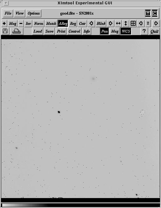
Here is a bad image taken on 19 March 2001 plotted at the same stretch. Notice the large number of warm pixels.
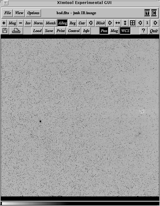
Here are some other diagnostic plots.
implot good.fits
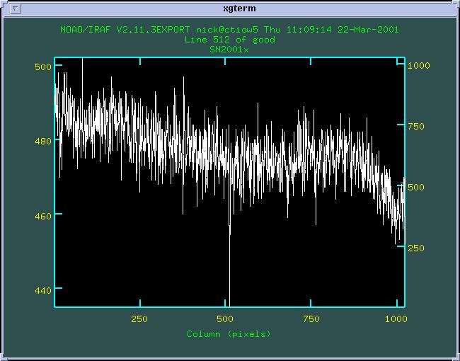
implot bad.fits
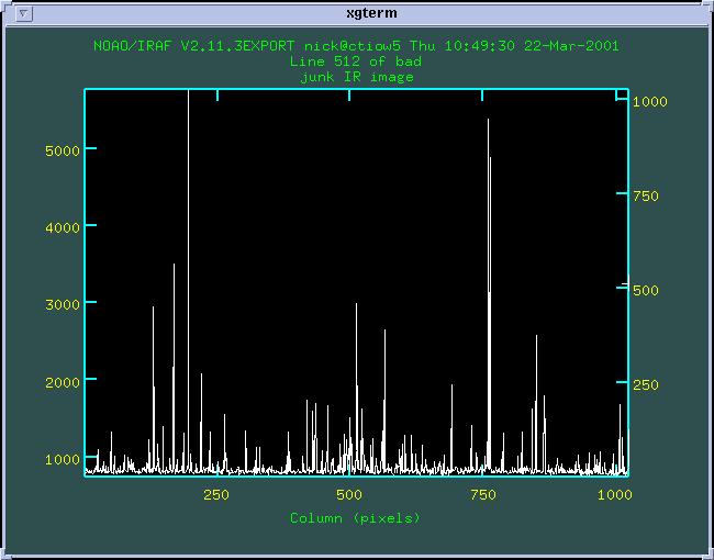
imhist good.fits z1=-100 z2=10000
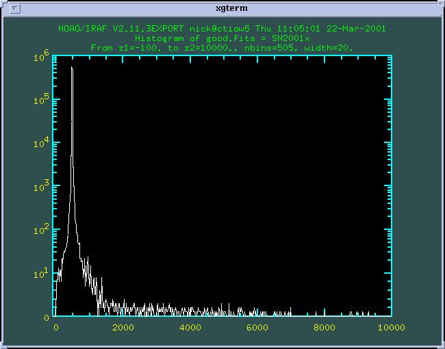
imhist bad.fits z1=-100 z2=10000
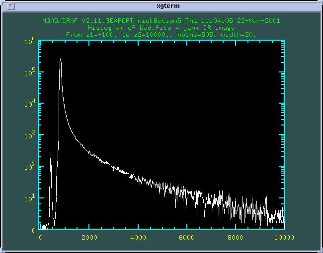
On 6/7 July 2001, I had the following image. This was the first J image in a sequence of JHK images.
There is clear ghosting on the chip. This ghosting disappeared over 10min or so. What I don't understand is that the previous images were taken some 20min before this one. This is the only case of ghosting I have seen and it really screws up the sky subtraction. This night also had variable warm pixels, although not as bad as above. The warm pixels appeared in the middle of a sequence of supernova exposures, right after the third 15arcsec offset, which seems to imply a problem with the electronics and not the coolant going off the detector.
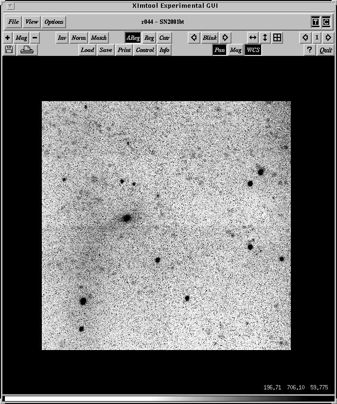
Good YALO reduced images from March 2001
The following images are the final reduction images for SN2001X. The data was taken from 20010323( 23/4 March 2001). The data were taken as:
The data reduction was described in the notes given in this web page. In particular, I reduced the JH data using a single averaged sky, averaged across the two dither positions. The K image was reduced keeping the two dither positions separate to reduce the fringing. I used flat fields taken at the two dither positions, and reduced the data to [OZF] keeping the dithers separate.
The supernova had the following approximate magnitudes in these data:
JHK = (3450,4100,3350 ADU/45s) = (14.9,14.7,14.4)
The reduced J image.
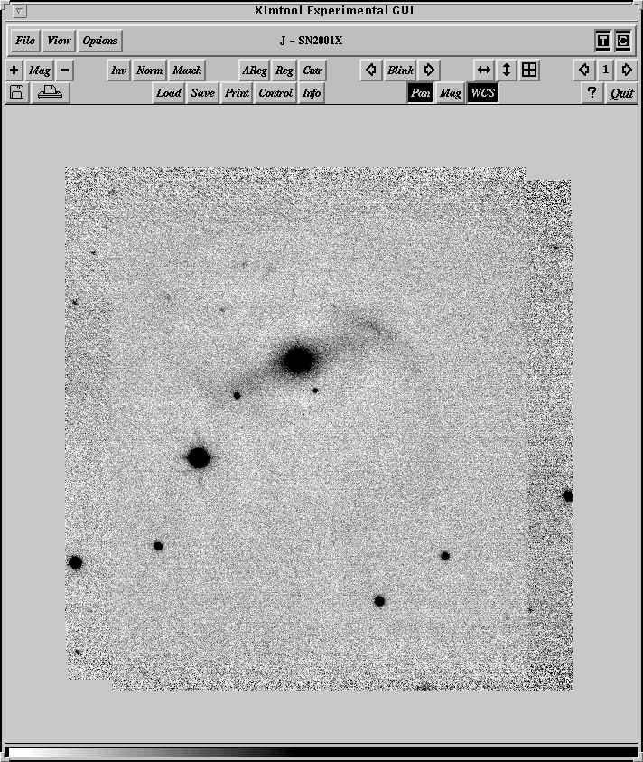
The H image. The dark edge on the right is a result of averaging all the skies together across dithers. If I reduced the H data for each dither independently, this edge would disappear.
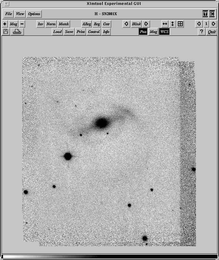
The K image. Note the absence of fringing. You can see a small amount of print-through in the skies as a vertical white streaks above and below the bright objects. This is because only 5 images went into the sky median.
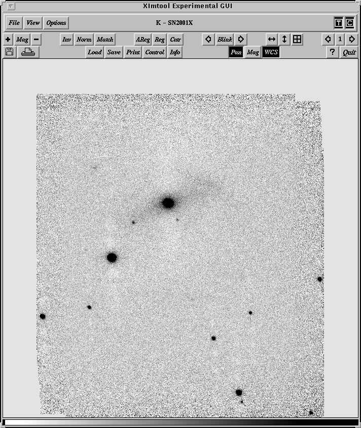
Here is what the K image looks like if the sky is averaged across all dither positions. Note the fringing and the obvious problems that remain with the vignetting. I am not convinced yet that the vignetted area in the image above is photometrically flat. The sky has subtracted but this does not mean that the photometry will be correct in that region. I will still assume that only for x<650 is the field photometrically flat.
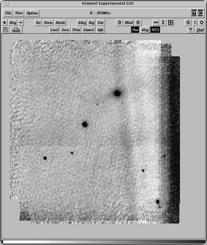
How to measure the sky brightness
We will measure the flux (in cts/sec) of stars of a given magnitude through a standard aperture. These fluxes will be corrected to above the atmosphere. An offset between the observed counting rate and standard magnitudes will be caculated. This will be done on a few frames per night of Landolt or E region standards. This zero-point must be recalculated for each new night.
For the object frames, we will calculate the modal value of all the pixels, correct this to 1 arc-sec square, and then convert this to a magnitude. We will *not* correct the object frames for extinction. Kevin can explain why.
We will measure about 6 nights per year over the last 5 years. We will then add these data to the data that Roger Leiton and Kevin Krisciunas have.
Make sure you have a directory like
(home)/uparm/ctio36/
or similar for ctio60, etc.
Edit and run setup:
setup:
set stdimage = imt1024
set uparm = /uw50/nick/uparm/ctio36/
set imdir = HDR$pix/
noao
ctio
nickcl
imred
digi
apphot
astu
ccdr
ccdred.instrument = "myiraf$cfccd.dat"
ccdred.ssfile = "myiraf$c36.sub"
task skyb = "nickcl$skyb.cl"
task skymag = "nickcl$skymag.cl"
task $sed = "$foreign"
loadit.format = "1024"
loadit.statsec = "*,*"
nstat.statsec = "*,*"
keep
IF YOU ARE STARTING A NEW NIGHT, DELETE THE FILE:
rm -f /tmp/skyb.dat
Separate the filters.
hsel obj*.imh $I,filters yes | sed s/.imh// | grep "'dia b'" | field - 1 > inb
hsel obj*.imh $I,filter2 yes | sed s/.imh// | grep v | sed s/v// > inv
Make sure that CTIO is listed as the observatory. Do:
hsel *.imh $I,observat yes
If not, run
hedit *.imh observat CTIO add+ ver- show+
Run setairmass to add UTMIDDLE keyword:
setairmass *.imh
Now run the first program, the sky brightness programs "skyb." This creates a file called /tmp/skyb.dat which contains the information needed for the nightly calculation of the zero-point of the photometric scale.
For skyb, change the following parameters depending on the telescope.
For the 36", 0.40"/pix. We use a standard radius of 7" or 7/0.4=17.5 pixels.
| (epadu = | 4.0) | CCD gain (e-/adu) | |
| (readnoi= | 3.2) | CCD read noise (e-) | |
| (annulus= | 17.5) | Inner radius of sky annulus | |
| (dannulu= | 10.) | Width of sky annulus | |
| (apertur= | 17.5) | Aperture radius |
To find the library mags, grep on:
head -1 /uw50/nick/daophot/library/ubvri.lib
grep ru152 /uw50/nick/daophot/library/ubvri.lib
etc. I open an new window, use SMALL type, and widen the window to fit one line per star. With this window I cut/paste the library magnitude so I never have to type it.
Select a field. make sure it is not at high airmass. Check the airmass as:
hsel @inv $I,airmass
Using "skyb", find the star, enter the library magnitude *carefully*, then mark the star. Exit by typing "q" twice while the image cursor is active.
Measure about 5-10 stars in at least two frames. Try to select fields that are near airmass 1.2. Don't go above 1.6.
The form of /tmp/skyb.dat is:
| #object | x | y | exptime | airmass | filt | nat_mag | err | stand_mag | |
| obj152 | 536.820 | 695.439 | 20. | 1.272 | diav | 17.242 | 0.004 | 13.866 | |
| obj152 | 416.543 | 699.798 | 20. | 1.272 | diav | 16.002 | 0.002 | 12.642 | |
| obj152 | 426.741 | 598.940 | 20. | 1.272 | diav | 17.813 | 0.007 | 14.425 |
You can check quickly the sky zeropoints as:
sort /tmp/skyb.dat col=6
grep diav /tmp/skyb.dat | filecalc STDIN "$9-$7" form="%7.2f"
grep diab /tmp/skyb.dat | filecalc STDIN "$9-$7" form="%7.2f"
For instance, the output looks like:
-3.80
-3.84
-3.27
-3.85
-3.84
If any of the mags look bad, edit the file /tmp/skyb.dat. You can comment out the bad value using a leading "#".
Now run "skymag." Make sure the read noise and gain are correct. Make sure that UT is set to UTMIDDLE. This parameter is set by "setairmass" so you have to have run that program. You also have to enter an airmass correction. This is to correct the *standard* stars in /tmp/skyb.dat and not the individual frames.
Most importantly - MAKE SURE THAT THE SECPIX IS CORRECT! SEE URL FOR TELESCOPES TO GET THE SCALE.
Run as:
skymag @inb extinct=0.22 out=skyb.dat
skymag @inv extinct=0.12 out=skyv.dat
cc> lpar skymag
| filein = | "@inb" | input image or image list |
| (ra = | "RA") | right ascension keyword |
| (dec = | "DEC") | declination keyword |
| (epoch = | "EPOCH") | epoch of coords keyword |
| (dateobs = | "DATE-OBS") | observation date keyword |
| (ut = | "UTMIDDLE") | universal time keyword |
| (airmass = | "AIRMASS") | airmass keyword |
| (exptime = | "EXPTIME") | exposure time keyword |
| (filters = | "FILTERS") | filters keyword |
| (secpix = | 0.4) | arcsecond per pixel |
| (sigma = | 10.) | sigma search window for mode |
| (gain = | 4.) | CCD gain (e-/adu) |
| (rnoise = | 3.2) | CCD read noise (e-) |
| (extinct = | 0.12) | extinction (mag/airmass)) |
| (photzp = | 25.) | photometric zeropoint |
| (binsize = | 1.) | bin size for histograms |
| (plotit = | yes) | plot the sky histogram? |
| (saveit = | yes) | save data to file? |
| (outfile = | "sky.dat") | sky mag file |
| (newfile = | no) | new file? if not, will append |
| (imglist = | "tmp$tmp.59lb") | |
| (mode = | "ql") |
The screen output of skymag is:
| #object | exptime | airmass | filter | ct/s | ct/s | mag_1 | mag_2 | zp | sig | N | |
| # | hist gaussian | ||||||||||
| # | hist gaussian | ||||||||||
| obj147 | 30 | 1.56 | diav | 8.38 | 7.82 | 21.18 | 21.26 | -3.21 | 0.02 | 5 | |
| obj152 | 20 | 1.27 | diav | 5.15 | 5.56 | 21.27 | 21.19 | -3.21 | 0.02 | 5 | |
| obj156 | 600 | 1.62 | diav | 156.16 | 157.02 | 21.26 | 21.25 | -3.21 | 0.02 | 5 | |
Here we have calculated the cts/s two ways - (1) we used the IRAF task histogram to estimate the peak and (2) we used a robust gaussian fit
to the data. It is my experience that these two numbers agree to better than 0.15mag usually. For the text output, we will only use the
Gaussian fit.
Note that the program also plots the histogram and the fit. Usually they are right on top of each other so there is not much to see. Run
the program and watch these fits for anything funny. You can also review the last fits by running gkimosaic, stepping through the data
with the space bar.
gkimosaic sky.gki nx=1 ny=1
The text output of skymag looks like:
| #obj | exptime | airmass | filter | UT | cts/sec | sky mag | |
| obj146 | 40 | 1.56 | diab | 1:15:16 | 2.90 | 22.30 | |
| obj151 | 30 | 1.28 | diab | 1:23:29 | 2.62 | 22.10 |
Check the output with graph. The first one plots against time, the second against airmass, third against UT.
fields skyv.dat 2,7 | graph poin+ rou+ szm=0.02 mar=circle logx+ tit="exptime"
fields skyv.dat 3,7 | graph poin+ rou+ szm=0.02 mar=circle tit="airmass"
fields skyv.dat 5,7 | graph poin+ rou+ szm=0.02 mar=circle tit="UT"
fields skyb.dat 2,7 | graph poin+ rou+ szm=0.02 mar=circle logx+ tit="exptime"
fields skyb.dat 3,7 | graph poin+ rou+ szm=0.02 mar=circle tit="airmass"
fields skyb.dat 5,7 | graph poin+ rou+ szm=0.02 mar=circle tit="UT"
We will create averaged sky brightness measurements after we have some experience. But for now, you can do a simple average as:
fields skyb.dat 7 | ave
fields skyv.dat 7 | ave
The idea is to create an image of the error in the shutter. The logic was borrowed from Stetson (thanks Peter!). We will create an image where every pixel is the increment in time that a 1s exposure is really seeing. That is, if a pixel has a value of 0.063, the 1s exposure actually was 1.063s at that position. Most of our iris shutters have errors of this level. Typically the shutter is open 0.08s more in the center and 0.06s in the corners.
As far as I can tell, the error is really constant. That is, in the center a 1s exposure is really 1.080s and a 5s exposure is 5.080s.
==>Shutter images:
6 20s dflats
5 20x1s focus frames.
The idea here is to alternate 20 sec dflats and 20 1 sec focus frames. I use the R filter with the cb filter and take domes for
this. Do this once during the run. 20s is the nominal time. You can change the time, but be sure to change the "shut1" script for any new integration time you get.
To do the sequence:
0. Turn on dome lights. Let them be on for at least 10min.
1. Set fnrows=0 in telpars. This means that there will be no shifts during the focus image. Set nfexpo=20. This means there will be 20 focus exposures in a single focus sequence.
telpars.fnrows = 0
telpars.nfexpo = 20
telpars.fdelta = 0
2. Take a 20sec R dome.
3. Take a focus frame.
Here we will set exposure time to 1 sec and take 20 exposures. The shutter will open and close 20 times. What I do is to start the focus sequence and hit ``RETURN'' 20 times. This focus frame should also be in R.
4. Take a 20sec R dome
5. Take a 20 x 1 sec focus
etc.
You should keep on doing this until you have at least 5 focus frames. Begin and end with the 20sec dome flats. This can be done in the afternoon. It only needs to be done once during the run. I take this many images because the FF tends to jump around.
1 dflat 20sec
1 focus 20x1sec
2 dflat 20sec
2 focus 20x1sec
3 dflat 20sec
3 focus 20x1sec
4 dflat 20sec
4 focus 20x1sec
5 dflat 20sec
5 focus 20x1sec
6 dflat 20sec
Average the 20x1 and 20 second images into test1 and test2.
If you are paranoid, you can also take 10x2s, 5x4s, whatever, to prove to yourself that the error is linear.
Cut and paste the following scripts.
shut1.cl:
#
# makes shutter image - change "20" for whatever your exptime is
# input:
# test1 = 20x1sec average (I used a straight median)
# test2 = 20sec exposure
#
# delta = 20(R-1)/(20-R)
#
imarith.pixtype = "real"
imarith.calctype = "real"
imarith.verbose = yes
imar test1 / test2 R
imar R - 1. temp1
imar temp1 * 20. temp1
imar R - 20. temp2
imar temp2 * -1. temp2
imar temp1 / temp2 temp3
fmedian temp3 shut 49 49 zmin=-1 zmin=1
hedit shut title "Shutter image" up+ ver-
imdel temp1.imh,temp2.imh,temp3.imh,R.imh
display shut 1 zs- zr- z1=-0.1 z2=0.1
#
beep
#
# the output image is a frame which has "delta t" in each pixel
# where delta t is the time (in seconds) from 1 second that the
# pixel actually saw. Thus if the value is -0.039, that means the
# pixel saw (1-0.039)s instead of 1 second. This image is input into
# task "shut2"
#
shut2.cl:
#
# task to create correction images for short exposures. These images are
# multiplicative. That is, if you have an image with a 4 sec exposure
# you would do:
#
# imar image * 4sec image
# hedit image SHUTCOR "Corrected by 4sec" add+ ver- show+
#
# my rule of thumb is that if the correction is less than 1%, forget it.
#
# inputs "shut" from script shut1
#
imarith.pixtype = "real"
imarith.calctype = "real"
imarith.verbose = yes
#
# 0.2 sec
#
imdel temp*.imh
imar shut * 0. temp1
imar temp1 + 0.2 temp1
imar shut + temp1 temp2
imar temp1 / temp2 0.2sec
hedit 0.2sec title "0.2sec correction" add+ up+ ver-
#
# 0.5 sec
#
imdel temp*.imh
imar shut * 0. temp1
imar temp1 + 0.5 temp1
imar shut + temp1 temp2
imar temp1 / temp2 0.5sec
hedit 0.5sec title "0.5sec correction" add+ up+ ver-
#
# 1 sec
#
imdel temp*.imh
imar shut * 0. temp1
imar temp1 + 1. temp1
imar shut + temp1 temp2
imar temp1 / temp2 1sec
hedit 1sec title "1sec correction" add+ up+ ver-
#
# 2 sec
#
imdel temp*.imh
imar shut * 0. temp1
imar temp1 + 2. temp1
imar shut + temp1 temp2
imar temp1 / temp2 2sec
hedit 2sec title "2 sec correction" add+ up+ ver-
#
# 3 sec
#
imdel temp*.imh
imar shut * 0. temp1
imar temp1 + 3. temp1
imar shut + temp1 temp2
imar temp1 / temp2 3sec
hedit 3sec title "3 sec correction" add+ up+ ver-
#
# 4 sec
#
imdel temp*.imh
imar shut * 0. temp1
imar temp1 + 4. temp1
imar shut + temp1 temp2
imar temp1 / temp2 4sec
hedit 4sec title "4 sec correction" add+ up+ ver-
#
# 5 sec
#
imdel temp*.imh
imar shut * 0. temp1
imar temp1 + 5. temp1
imar shut + temp1 temp2
imar temp1 / temp2 5sec
hedit 5sec title "5 sec correction" add+ up+ ver-
#
# 6 sec
#
imdel temp*.imh
imar shut * 0. temp1
imar temp1 + 6. temp1
imar shut + temp1 temp2
imar temp1 / temp2 6sec
hedit 6sec title "6 sec correction" add+ up+ ver-
#
# 7 sec
#
imdel temp*.imh
imar shut * 0. temp1
imar temp1 + 7. temp1
imar shut + temp1 temp2
imar temp1 / temp2 7sec
hedit 7sec title "7 sec correction" add+ up+ ver-
#
# 8 sec
#
imdel temp*.imh
imar shut * 0. temp1
imar temp1 + 8. temp1
imar shut + temp1 temp2
imar temp1 / temp2 8sec
hedit 8sec title "8 sec correction" add+ up+ ver-
#
# 9 sec
#
imdel temp*.imh
imar shut * 0. temp1
imar temp1 + 9. temp1
imar shut + temp1 temp2
imar temp1 / temp2 9sec
hedit 9sec title "9 sec correction" add+ up+ ver-
#
# 10 sec
#
imdel temp*.imh
imar shut * 0. temp1
imar temp1 + 10. temp1
imar shut + temp1 temp2
imar temp1 / temp2 10sec
hedit 10sec title "10sec correction" add+ up+ ver-
#
# 11 sec
#
imdel temp*.imh
imar shut * 0. temp1
imar temp1 + 11. temp1
imar shut + temp1 temp2
imar temp1 / temp2 11sec
hedit 11sec title "11sec correction" add+ up+ ver-
#
# 12 sec
#
imdel temp*.imh
imar shut * 0. temp1
imar temp1 + 12. temp1
imar shut + temp1 temp2
imar temp1 / temp2 12sec
hedit 12sec title "12sec correction" add+ up+ ver-
#
#
# 13 sec
#
imdel temp*.imh
imar shut * 0. temp1
imar temp1 + 13. temp1
imar shut + temp1 temp2
imar temp1 / temp2 13sec
hedit 13sec title "13sec correction" add+ up+ ver-
#
#
# 14 sec
#
imdel temp*.imh
imar shut * 0. temp1
imar temp1 + 14. temp1
imar shut + temp1 temp2
imar temp1 / temp2 14sec
hedit 14sec title "14sec correction" add+ up+ ver-
#
#
# 15 sec
#
imdel temp*.imh
imar shut * 0. temp1
imar temp1 + 15. temp1
imar shut + temp1 temp2
imar temp1 / temp2 15sec
hedit 15sec title "15sec correction" add+ up+ ver-
#
#
# 16 sec
#
imdel temp*.imh
imar shut * 0. temp1
imar temp1 + 16. temp1
imar shut + temp1 temp2
imar temp1 / temp2 16sec
hedit 16sec title "16sec correction" add+ up+ ver-
#
#
# 17 sec
#
imdel temp*.imh
imar shut * 0. temp1
imar temp1 + 17. temp1
imar shut + temp1 temp2
imar temp1 / temp2 17sec
hedit 17sec title "17sec correction" add+ up+ ver-
#
#
# 18 sec
#
imdel temp*.imh
imar shut * 0. temp1
imar temp1 + 18. temp1
imar shut + temp1 temp2
imar temp1 / temp2 18sec
hedit 18sec title "18sec correction" add+ up+ ver-
#
#
# 19 sec
#
imdel temp*.imh
imar shut * 0. temp1
imar temp1 + 19. temp1
imar shut + temp1 temp2
imar temp1 / temp2 19sec
hedit 19sec title "19sec correction" add+ up+ ver-
#
#
# 20 sec
#
imdel temp*.imh
imar shut * 0. temp1
imar temp1 + 20. temp1
imar shut + temp1 temp2
imar temp1 / temp2 20sec
hedit 20sec title "20sec correction" add+ up+ ver-
#
beep
shutcor.cl:
#
# stupid script to make a task to correct for shutter errors
# assumes you have made images which you multiply into your data
# to take out shutter error, image of the form 1sec,0.5sec,20sec, etc.
# task shutcor = /uw50/nick/nickcl/shutcor.cl
#
procedure shutcor (images)
string images { prompt = 'input images' }
real itmax {20., prompt='Maximum integration time for corretion'}
struct *imglist
begin
string imgfile,img,tempfile,imcor1,imcor2,s1,s2,clout
real exptime
task $sed = $foreign
delete("tmp$tmp*", >> "dev$null")
imgfile=mktemp("tmp$tmp1")
tempfile="shutc.cl"
imglist=imgfile
hselect(images, "$I", yes, >> tempfile)
sed("s/.fits//",tempfile, >> imgfile)
delete(tempfile)
clout = "scor.cl"
delete(clout, >>& "dev$null")
while (fscan (imglist, img) != EOF) {
hselect(img,"exptime",expr=yes) | scan(exptime)
if (exptime > itmax) {
goto CONTINUE
}
imcor1=str(exptime)//"sec"
print(imcor1) | sed("s/\\\.sec/sec/") | scan(imcor2)
s1="imar "//img//" * "//imcor2//" "//img
s2="hedit "//img//" SHUTCOR "//'"Corrected by '//imcor2//'"'//" add+ up+ ver- show+"
print(s1, >> clout)
print(s2, >> clout)
CONTINUE:
}
delete(imgfile)
end
Links
[1] http://www.ctio.noao.edu/noao/content/15-m-october-2001
[2] http://www.ctio.noao.edu/noao/sites/default/files/telescopes/smarts/bvriu.clb
[3] http://www.ctio.noao.edu/noao/sites/default/files/telescopes/smarts/riv.clb
[4] http://www.ctio.noao.edu/noao/sites/default/files/telescopes/smarts/rz.clb
[5] http://cadcwww.hia.nrc.ca/cadcbin/wdbi.cgi/astrocat/stetson/query
[6] http://www.astronomy.ohio-state.edu/YALO/news.html
[7] http://www.ctio.noao.edu/noao/sites/default/files/telescopes/smarts/shut.gif
[8] http://www.ctio.noao.edu/noao/sites/default/files/telescopes/smarts/shut_cut.gif