


This operation is normally conducted every 2 years in average during the winter shut-down of August.
Blanco Aluminization test 2009 summary
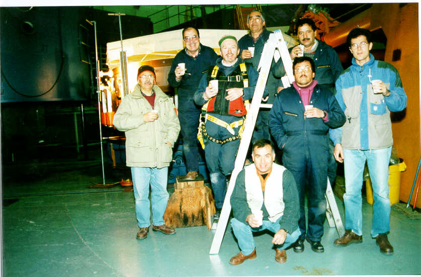
The entire process takes about 6 days (from the moment the mechanics team start until they leave the telescope ready for optical alignment). This is a picture of the 1998 aluminizing team.
Before the aluminizing chamber (start with the mirror set up on its pedestal in the washing area)
Inside the aluminizing chamber
This is done ideally with 6 people: 3 outside the mirror, 2 inside the central hole, 1 preparing materials.
Here is a list of materials. THINK SAFETY! Wear plastic suit all the time. Wear heavy gloves, goggle and respiratory mask when manipulating acids.
Have a plan for what to do in case of acid accident.
A.0. Pour natural sponges in a bath of HCl+H2O (to disolve any residuals of shells), rinse with water and cycle 5 times in washing machine.
A.1. For rough degrease: 200 gr of soap into 10 liters of filtered water (poured into 3 buckets)
A.2. For removing aluminium : 10 liters HCl + 10 liters filtered water + 200 grams CuSO4. !!CHANGE: a 15% HCl solution is enough (see how to apply it below)!!
A.3. For final degrease: 1 kg KOH into 20 liters of filtered water
A.4. Clean the mirror with CO2 snow, measure reflectivity and photograph mirror
A.5. If necessary, lay lab wipes on oil spots to absorb oil
A.6. Wear surgical gloves
A.7. From now onto the drying phase, ALWAYS keep the mirror wet.
Rinse entire mirror with filtered water (3 hoses) for 5 min. NO contact.
A.8. Pour soap onto entire mirror around the circumference. NO contact. Rinse with filtered water. REPEAT this step twice.
A.9. Blot mirror with soapy sponges using only the weight of the sponge. NO wiping. 3 people on outside of mirror make 2 complete circles. 2 people in the central hole make 3 complete circles.
A.10. Wash sides of mirror with soap and dedicated sponge NOT to be used on mirror optical surface.
A.11. Rinse the entire mirror with filtered water.
A.12. REPEAT step A.9 to A11.
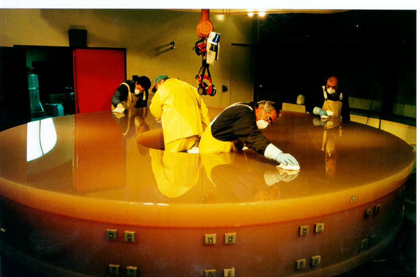
Figure 1: Mirror preparation & washing
B.1. Wear new surgical gloves + heavy gloves + goggle + respirator
B.2. One person pours HCl/CuSO4 around circumference of mirror while the 5 others drag-wipe with balls of cotton. Each cotton ball is used only for a maximum of 3 drag-wipe actions then replaced. Continue until aluminium is removed. !!CHANGE: cover the mirror with Kimwipes and pour HCl solution on them, they will keep the acid longer in contact with the coating and dissolve it without the need for a large quantity of acid!! Residual Al spot can we drag-wiped individually with a Kimwipe ball.
B3. Rinse with filtered water until pH is neutral. Rinse 2 minutes more with filtered water.
B4. Change to clean surgical gloves
B.5. One person pours KOH around circumference of mirror while the 5 others drag-wipe with cotton balls. Each cotton ball is used only for a maximum of 3 drag-wipe actions then replaced.
B.6. Rinse with filtered water until pH is neutral.
B.7. REPEAT steps B.5 to B.6
B.8. Rinse with filtered water 2 minutes more. Rinse carefully the mirror edge and the radial support mounts and holes.
C.1. Change to clean surgical gloves AND dust mask
C.2. Rinse with 50 liters DOUBLE distilled water pouring around the circumference. Check out that water flows uniformly on the surface, not leaving 'holes'that would be signs of broken surface tension of the liquid passing on a still-contaminated area.
C.3. 6 people using nozzle guns blow dry nitrogen from the outer diameter to the inner, making sure the water drops flows uniformly radially inward (look at them against the lights on the other side of the mirror. Dry as fast as possible to avoid water drying on its own. No contact with mirror during that phase. Bidistilled water is clean enough that the process doesn't leave water marks. Perform the breath test to detect any drying or contamination spots in any suspicious areas (breath gently on the mirror -dry your mouth first!- and watch out any pattern on the surface covered with moisture).
C.3. BIS. Old procedure: Have at least large 50 balls of Kimwipes ready and someone preparing more if necessary. They must be thick and wide, bigger than your hand. Rub (for the first time in the entire process) the mirror applying about 1-2 kg force on the Kimwipes balls. Do not overdo it! M he ball slowly to suck the water. Use each ball ONLY FOR ONE drag-wipe action then replace it (this is very important!!!). Work moving regularly around the mirror. As the mirror dries, you will have to work faster. Constantly check the entire mirror surface for areas that need attention. MAKE SURE your (dirty) sleeves are not touching the glass when you dry reaching far with your arm!! DO NOT let the mirror dry on its own! DO NOT wipe dry areas! Use Balzers virgin optical cotton cloth for touch ups. Check any visible stains and streaks with bright light and different viewing angles. It is hard to make the mirror better but easy to make it worse.
C4. Dry sides of the mirror and holes of the radial support mounts with Kimwipes. Use dry nitrogen to CAREFULLY blow out holes. Take care not to spray water on the optical surface.
C5. Hang up mirror in its hook. Clean with acetone the bottom of the mirror especially the 3 pads. Dry bottom of mirror with Kimwipes. DO A THOROUGH cleaning of all the non optical surfaces of the mirror for complete degreasing and drying.
C.6. Setup mirror on aluminizing tank floor. Blow off dust with CO2: MAKE ABSOLUTELY sure the substrate is free of dust (other wise the coating will be full of pinholes). Put 4 clean microscope test plates (coating witness samples) on edge of mirror. Seal tank.
Note: units used are : 1.3x10⁻⁶ atm = 1 micron (Hg) = 1 millitorr (=0.13 Pa)
Vacuum gauge positions: (to be checked)
1 is chamber
2 is holding pump
3 and 4 are the diffusion pumps
5 is roughing pump
Be careful: do not disconnect a vacuum sensor turned ON. Let any pump run for 1 min (listen the noise) before turning ON any vacuum gauge.
We indicate a typical elapsed time.
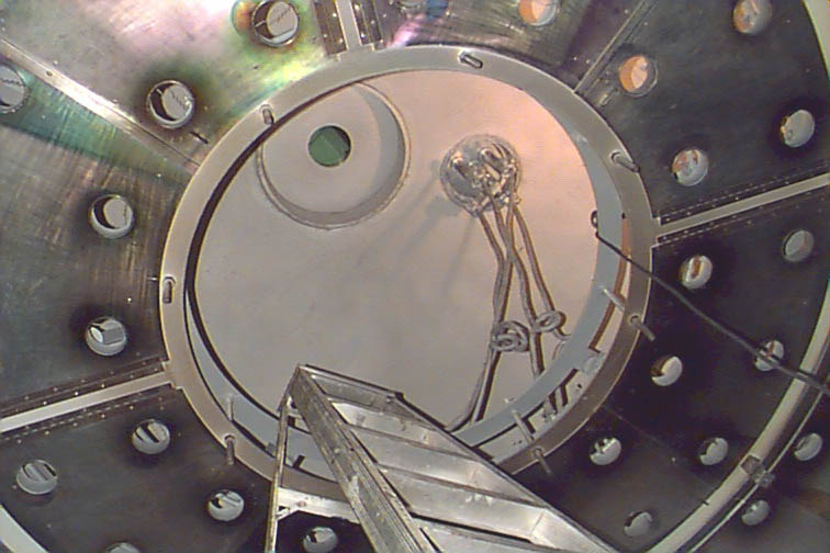
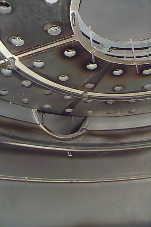
See pictures of the inside of the chamber: (Figure 2) general view of the chamber ceiling where you can recognize : the filaments in the round holes cut in the baffle sheet, the upper window used for checking the evaporation rate of aluminium and the cable feed-though port; (Figure 3) close view showing: the 4 concentric filament annuli (number of filaments per ring, from outermost to innermost: 36, 32, 20, 16 = 104 in total), the glow discharge ring (between annulus 2 and 3), part of the entrance conduit of one diffusion pump, the nitrogen pipe (near the bottom).
|
Figure 2: Inside the chamber |
Figure 3: Inside the chamber |
A.1. Work inside the chamber with clean white suit, gloves and shoes protectors. Wash the internal walls, windows and chamber floor with acetone (DON'T remove the side windows, it is hard to re-seal them). Chase any greasy spots!
A.2. Wash with HCl (strip off the aluminium) the feed-through cables contacts, the holding ring insulator.
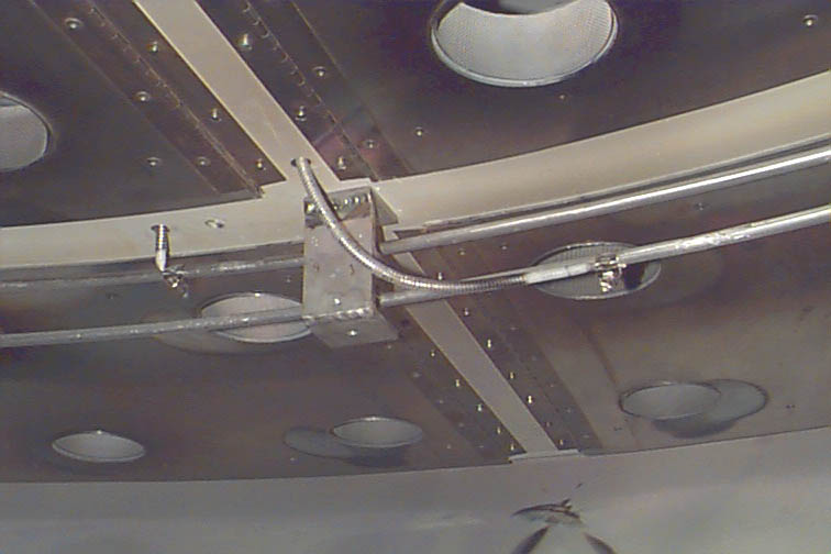
Figure 4
A.3. For better thickness uniformity, it is recommended to put filaments only in the outer rings. ±9% uniformity is reached that way (versus ±27% with all the arrays!). Check carefully all the filaments and replace the damaged ones: knock them with the finger to see if they don't break, they must be straight when loose (i.e. unstressed), not covered with blobs of aluminium. The filaments shall not touch the baffle mesh (to avoid short circuits) and be all at the same distance above the baffle (0.25 to 0.5"). IMPORTANT: tighten the filaments with a torque wrench to about 15 in-lbs so that the current that flows in them is uniform.
A.4. Hang 3 aluminium clips at both extremities of each filaments
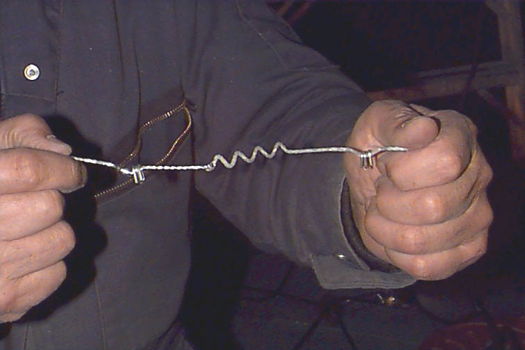
Figure 5: Filaments
A.5. Clean and lubricate the chamber Orings with high-vacuum grease. Don't lubricate the entire flange (but just the Oring). Don't put grease in excess! Close the chamber and put the C-clamps around the perimetral flange.
A.6. Run a typical vacuum sequence as described in B.1 to B.44 with 30 minutes minimum of glow discharge and eventually filament heating -but NOT LOADED with Aluminium clips!- to outgass them all (especially the new ones).
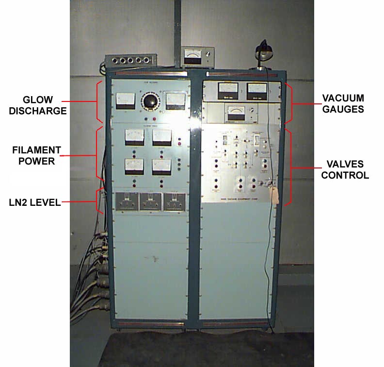
Figure 6: Control Panel
Most useful schematic diagram of the valves
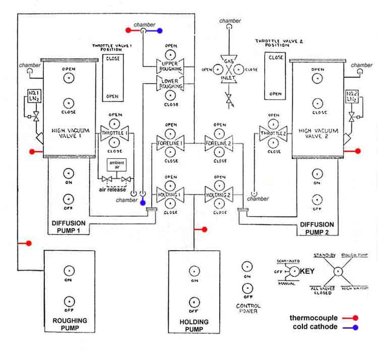
Figure 7: Diagram of the valves
Install the mirror and the coating monitor in the chamber (check that it works!). Put test plates on the edges of the mirror along the perimeter. Close the chamber and put C-clamps.
B.1. Connect flexible pipe of roughing pump to chamber (clean and lubricate Oring) and loosen the 2 adjusting rods.
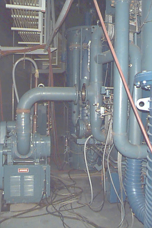
Figure 8
B.2. Connect 3 cylinders of liquid nitrogen (N2): one on each diffusion pump, one for the internal circuit (Meisner trap)
B.3. Open air valve in lateral wall (red flexible pipe)
B.4. Connect water lines to the coating monitor. Open water circuit (diffusor cooler): 2 valves -input/output- on pipes in backside wall ; (roughing pump is cooled with oil)
B.5. Check air pressure on diffusion pump: must read 70-75 psi (compressor is 100psi and feeds all valves)
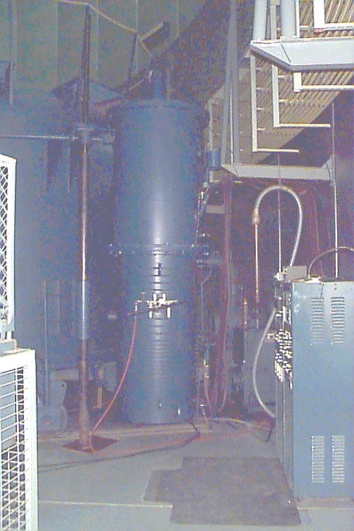
Figure 9
B.6.1. Connect roughing pump to energy on the wall (and unplug the M floor 'helicopter' fan). Turn ON air extractor on P floor (otherwise smoke will come out the roughing pump grey pipes).
B.6.2. Check switches: "manual" (key) and "all valves closed" (black knob). TURN ON power of control panel.
B.7. Test-cycle all valves (open/closed). The holding pump must be ON for the holding valves to work. Throttle valves leds don't shine (just watch the meter). Leave them all CLOSED including the mechanical needle valve for air inlet during glow discharge.
B.8. 0min: TURN ON roughing (mechanical) pump and immediately open foreline valves 1 and 2 (this starts pumping the diffusion pumps).
B.9. When diffusion pumps are below 20 microns (35 at least), TURN ON holding pump.
B.10. When holding pump is below 20 microns, close foreline valves 1 and 2, and open holding valves 1 and 2. Check vacuum in diffusion pumps (should remain the same at 20 microns). TURN OFF roughing pump (the holding pump is now holding the vacuum in the diffusion pumps).
B.11. TURN ON diffusion pumps 1 and 2 (it won't work if the water flow is below 3 GPM or if the diffusion pump pressure is above 25 torrs). TURN ON liquid level controllers (LN2 to diffusion pumps) and open slowly the 2 nitrogen cylinders valves (20 psi) to avoid freezing the controllers. Leave them open.
B.12. When the roughing line is at atmosphere, TURN ON the roughing pump and immediately open upper and lower roughing valves if not already opened (the roughing pump is now pumping the chamber). Check no excessive heat of diffusors.
B.13. Fan of roughing pump will power off (NOISE) automatically after 25 minutes, sign that vacuum is getting better.
B.14. 45min: When chamber pressure is around 20 microns, close upper and lower roughing valves. If vacuum in chamber doesn't seem to progress below 25 microns after some time, turn on the more reliable high vacuum gauge (cold cathode).
B.15. When the roughing line reads 10 microns, open foreline valves 1 and 2 (the roughing pump is now pumping the diffusion pump as is the holding pump).
B.16. Open throttle valves 1 and 2. Open high vacuum valves 1 and 2, waiting about 1 min between the aperture of both valves in order to prevent oil backstreaming (the diffusion pumps are now pumping the chamber).
B.17. Close holding valves 1 and 2. TURN OFF holding pump.
B.18. TURN ON high vacuum gauges (if the cold cathode is dirty, it might takes a while before it starts reading). When chamber reaches 5x10⁻⁵ torrs, TURN ON nitrogen cylinder valve for Meisner trap and corresponding liquid level controller.
B.19. 1h45min: When chamber reaches 1x10⁻⁵ torrs, reverse the process to be able to do the GLOW DISCHARGE:
B.20. Turn off high vacuum gauges, close high vacuum valves 1 and 2 and throttle valves 1 and 2.
B.21. TURN ON holding pump, close foreline valves 1 and 2. Open holding valves 1 and 2 (the holding pump pumps the diffusion pump). Check pressure in diffusion pumps.
B.22. Open upper and lower roughing valves (the roughing pump pumps the chamber).
B.23. Open air inlet needle valve by 1.25 turn and use the inlet switch to set and maintain the chamber pressure at 35 microns, which is the appropriate pressure to run the glow discharge safely. Glow discharge provides outgassing of the substrate through heating, conversion of organic substances into their volatile components and desorption of films through electrons impact.
B.24. Turn on glow discharge controller. Slowly raise the current to 3 Amps in 2 minutes. Voltage will read about 3000 Volts (if the meter works!). A uniform purple color will be visible inside the chamber. If pink arcs or flashes show up (usually at 30mic), the pressure is too low, so open air inlet valve to raise the pressure back to about 35-40 microns. The ionized air will bombard the residual sticky hydrocarbons and, by transfer of kinetic energy, help to remove them from the surfaces (especially the mirror's). Monitor the discharge for 10 to 30 minutes. Reduce the current to 0 in 30 seconds. CLOSE the needle valve by hand.
Figure 10
B.25. 2h20min: close upper and lower roughing valves. When the roughing line reads 10 microns, open foreline valves 1 and 2.
B.26. Open throttle valves 1 and 2. Open high vacuum valves 1 and 2 with the same 1-min waiting precaution (the diffusion pumps are now pumping the chamber again).
B.27. Close holding valves 1 and 2. Turn off holding pump.
B.28. TURN ON high vacuum gauges. They should read 1x10⁻⁵ torrs in a few minutes.
B.29. 2h45min: cold cathodes should read around 8x10⁻⁶ torrs.
B.30. 3h30min: cold cathodes should read at least around 6x10⁻⁶ torrs, which is just enough to aluminize (the higher the vacuum beyond that limit, the better):
B.31. Turn off all kinds of fans (Pump floor for example) to avoid vibrations in the floor.
B.32. 4h40min: Install the coating monitor on top of the chamber near the window and check its parameters. With the 4 filament arrays, the chamber deposits an uneven film: 65% at r=20", 100% at r=45" and 50% at r=80". The tickness monitor is measuring at r=20", so in order to obtain 1000 Angstroms maximum thickness on the mirror, the firing should be stopped when the thickness monitor indicates 650 Ang. After you power off the filaments, the evaporation still goes on for about 70 Ang., so you should power off at about 580 Ang.
B.35. Let the filaments cool for 15 min.
B.36. TURN OFF all gauges control.
B.37. CLOSE high vacuum valves 1 and 2. CLOSE throttle valves 1 and 2. TURN OFF liquid level controllers.
B.38. CLOSE foreline valves 1 and 2. TURN OFF roughing pump. TURN ON holding pump.
B.39. When pressure in holding lines is below 20 microns, OPEN Holding valves 1 and 2. TURN OFF Diffusion pumps.
B.40. Release slowly for 1min air to the chamber (big manual valve in the back) then open it completely. Let air get in 20min.
B.41. UNPLUG the LN2 cylinders and clean the lines with compressed air.
B.42. When the chamber is at atmospheric pressure, disconnect the head of the roughing pump and open the chamber. Remove test plates and mirror. Close the chamber.
B.43. When the diffusion pumps are cool to touch, CLOSE holding valves 1 and 2. TURN OFF Holding pump. TURN OFF control power. TURN OFF key switch.
B.44. TURN OFF air and water to diffusion pumps. CLOSE big manual air release valve.
** The goal is to deposit a layer of Aluminium of 950 Angstroms (±5%) of thickness on the glass (the chamber is capable of ±10% thickness uniformity when using the outer array only). Above 1000 Ang. thick, the coating will start showing more and more surface roughgness which will increase scatter. A thickness of at least 500 Ang. is required to maintain the transmission through the coating below 0.1%. The faster the evaporation rate is better because the vapour of Aluminium doesn't get much time to be contaminated with oxygen or other residual gases in the chamber. A rapidly deposited coating is more compact and show less surface roughness. Once the Al coating enters in contact with air, a 30 to 40 Angstroms-thick layer of Aluminium oxide (Al2O3) will quickly form on the surface and protect the Aluminium from tarnishing. This layer also hardens tremendously the Al (Knoop hardness of 2100 kg.mm-2 compared to 140 kg.mm-2 for bulk Al). Final experiments to check quality of aluminizing: look for water marks; put some sticky tape on edge of mirror and watch for aluminium peeling off; look at bright incandescent bulb from the edge of the mirror through the glass: the bulb should barely be visible. Inside the chamber, check the status of all the filaments : broken ones, clips not melted, eventual short circuits,... which will give you a better idea of the thickness uniformity.
Note: chemical processes in the obtention of the vacuum
Schematic diagram of the diffusion pump
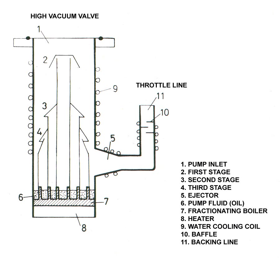
Figure 11
Maxime Boccas, last revision on 2th of August 2000.


