This figure shows the optical layout of the MASS-DIMM instrument.
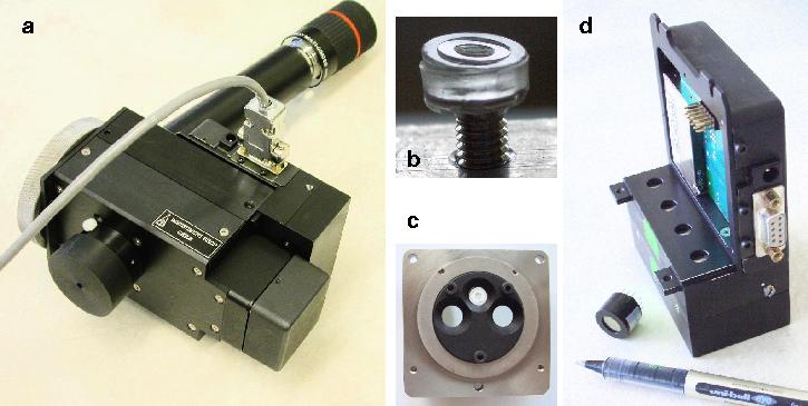
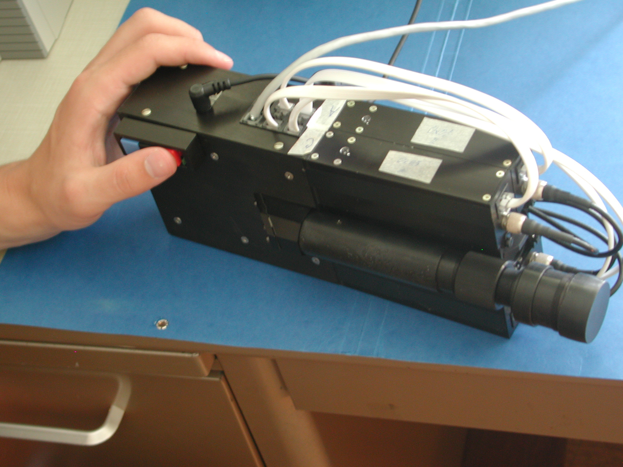
Some pictures of the MASS-DIMM instrument: overall view (a, CCD detector is replaced by a cap), plastic segmentator replicated on top of the M3 screw (b), the pupil-plane unit with a mask (d, two holes for DIMM apertures and one for MASS segmentator), and the electronics module with a tiny PMT (d, a pen is inserted for scale).
The first MASS instrument (2002)
The MASS turbulence profiler consists of:
- Detector box with 4 PMTs, optics and electronics
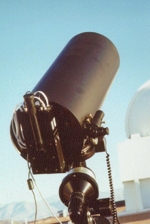
- Feeding telescope with 14 cm clear (unobstructed) aperture made at the Lytkarino Optical factory [picture]
- Personal computer with the MASS programm called Turbina.
![[picture]](truba.jpg)
The optical layout of the MASS detector box. Light from the feeding telescope is reflected from the diagonal mirror 2 and is focussed at the plane of the disk 3 where interchangable focal apertures are located. The disk is rotated by stepper motor under computer control.
The beam then goes through the Fabry lens 4 which forms the image of telescope mirror (exit pupil) on the segmentator 7. The segmentator consists of ring-shaped mirrors which deflect circular parts of the pupil image to refocussing spherical mirrors 8A-8D that deliver the four beams to the photocathodes of the PMTs A, B, C, D. In front of the segmentator, the beamsplitter 5 with dichroic layer diverts red wavelengths to the guiding assembly (mirror 9a, lens 9b, ocular 10a which can be replaced by a small TV camera). The green-blue part of the spectrum is used for scintillations measurement, filter 6 defines the spectral response curve.
 |
 |
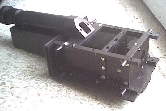
| Partially assembled box without PM modules and cover. | Assembled instrument viewed from the bottom |
 |
 |
| Assembled detector box | Feeding telescope with MASS at Cerro Tololo |
Real-time display of the MASS control software, TURBINA, at the end of the night of March 22/23, 2002. UT scale starts at 0h, March 22. Few glitches are caused by bad guiding. Top to bottom:
- Scintillation index in the smallest aperture, A
- Differential scintillation index in apertures A and B
- Free-atmosphere seeing, arcseconds
- Isoplanatic angle, arcseconds
- Cn2 profile: the integrated intensities of 5 atmospheric slabs at altitudes from 1 to 16 km in [m^1/3] are plotted.