
R-C Spectrograph is retired.
A reference manual describing the spectrograph optics, gratings, camera, CCD, etc.
The R-C grating spectrograph is used at the f/7.8 R-C focus of the Víctor M. Blanco 4-meter Telescope where the scale is 6.56 "/mm. It is identical in design to the one at Kitt Peak National Observatory and, as far as possible, in operation. The distinguishing feature of these spectrographs is their large beam size (point-source beam size is 152mm). As a result, higher dispersion than usual for Cassegrain spectrographs is available, along with excellent spatial resolution for observations of extended objects. All functions of the spectrograph can be controlled remotely by the data acquisition computer, permitting convenient and efficient operation.
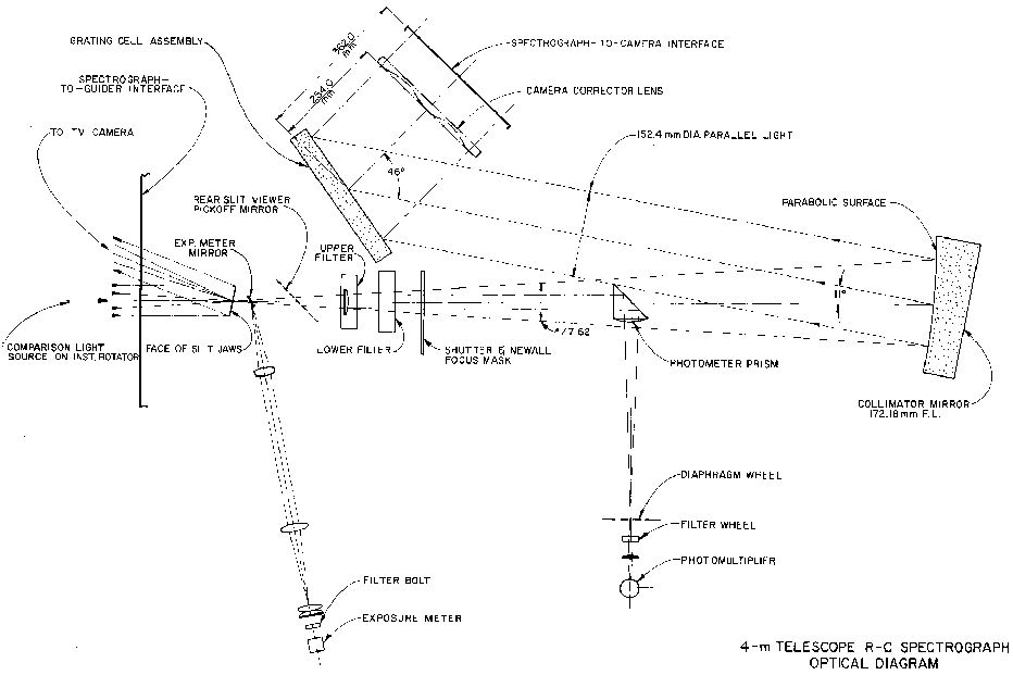
This is a basic walk-through of the spectrograph. Refer to the optical diagram below. The basic elements (in the order they get hit by incoming photons) are:
| Slit/Decker Filter Collimator Grating Camera & CCD |
 [1] [1] |
Acquisition & Guiding [2]
Description of the Field Acquistion and Slit Viewing TV & the Offset Guider
R-C Spectrograph Slit & Decker
The entrance slit has a length of 50 mm. Its width has a range from closure to 50 mm. One second of arc corresponds to approximately 150µ and, with the Blue Air Schmidt camera and Loral 3K×1K CCD now used with the R-C spectrograph, a 1" slit projects to 2 pixels on the CCD for small grating tilts. Because of anamorphic magnification, the 2-pixel projected slit width will be greater than 150µ at large grating tilts. Here is a plot showing the 2-pixel projected slit width as function of grating angle readout.
The decker plate for defining the length of the slit is normally left in the fully open position. With the decker fully open, the field of view is limited to 50 mm, 328 arcseconds, by the length of the slit. For reference the other available decker positions are:
| No. | mm | arcsec | |
| 1 | 1.86 | 12 | |
| 2 | 3.71 | 24 | |
| 3 | 7.42 | 49 | |
| 4 | 14.85 | 97 | |
| 5 | 30.98 | 203 |
Michael Keane (mkeaneATnoao.edu)
Jack Baldwin (jbaldwinATnoao.edu)
Two filter bolts that each can hold four filters and a clear position are available. The lower filter bolt contains neutral density filters; the upper filter bolt contains either order-sorting [3] filters or additional neutral density filters. An additional filter holder for a single order-sorting [3] filter can be manually inserted into the beam if required.
Note that any filters used are all located behind the slit, and so will alter the collimator focus. The final collimator focus value should be determined with the desired filters in place.
Michael Keane (mkeaneATnoao.edu)
Jack Baldwin (jbaldwinATnoao.edu)
The collimator mirror is an off-axis (11°) paraboloid of 225mm diameter and 1161mm focal length. The point-source beam size is 152mm.
There are two collmators available for the R-C spectrograph on the Blanco 4-m, the "blue" collimator and the "red" collimator. The difference is that the blue collimator is Aluminium coated, while the red is silver coated.
NOTE: As of 20 Apr 2000, the red collimator is not available because the coating was damaged. We are investigating recoating it, but in the mean time, only the blue collimator is available.
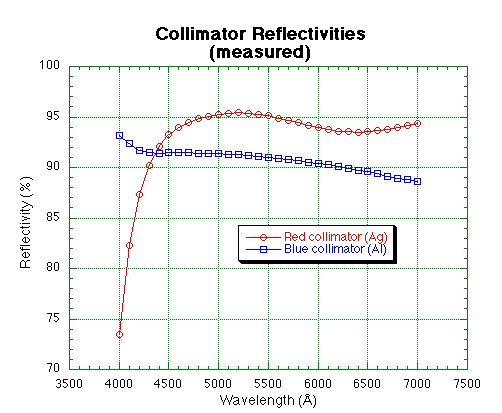
The plot below shows the last measured reflectivities of the two collimators.

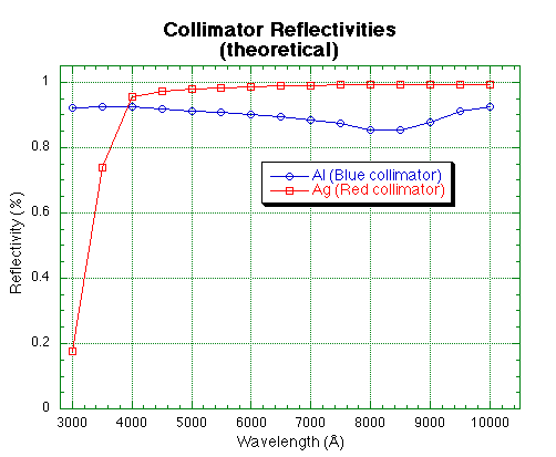
Just for reference, the following plot and table show the catalog reflectivities for Ag and Al over the optical spectral range. This shows the theoretical best performance of the two coatings, NOT the real values.

Last update: April 24, 2000
Chris Smith (csmithATnoao.edu)
Knut Olsen (kolsenATnoao.edu)
The 4.0-m R-C spectrograph has a fixed 46° angle between the optical axes of the collimator & camera. For sufficiently large grating tilts e.g., observing at high dispersion, the beam coming from the collimator can overfill the grating resulting in the loss of a small amount of light. For the 4.0-m R-C spectrograph, the collimated beam begins to overfill the grating for tilts > ~30.3° (readout < ~36.6°).
The amount of light which may be lost due to overfilling the grating is almost always neglible, typically a few percent. In practice, this small loss would be more than offset by the abliity to observe using a wider slit while preserving spectral resolution that results from the anamorphic demagnification [4] at large grating tilts.
At present, there are thirteen 203×254 mm gratings available. Their nominal specifications are listed below, along with dispersion, and coverage in 1st order available with the BAS + L3K.
| 1st Order | |||||
|---|---|---|---|---|---|
| Grating | l/mm |
Blaze [1] (A) |
Wavelength Coverage (A) |
Dispersion
(A/pixel) |
Notes |
| G250 | 158 | 4000 | 11431 | 3.75 | |
| G400 | 158 | 8000 | 11431 | 3.75 | 2 |
| G510 | 300 | 10000 | 5999 | 2.01 | 2,3 |
| G181 | 316 | 7500 | 5708 | 1.91 | |
| KPGL2 | 316 | 4400 | 5708 | 1.91 | |
| KPGL3 | 527 | 5500 | 3417 | 1.16 | |
| G420 | 600 | 8000 | 2981 | 1.02 | 3 |
| KPGL1 | 632 | 4200 | 2872 | 0.95 | |
| KPGLF | 632 | 8200 | 2872 | 0.95 | |
| G450 | 632 | 11000 | 2872 | 0.95 | |
| KPGLD | 790 | 8500 | 2290 | 0.75 | |
| KPGLG | 860 | 11000 | 2101 | 0.68 | |
| G380 | 1200 | 8000 | 1563 | 0.48 | 3 |
Notes:
                                                       R-C Spectrograph
                                                Grating Relative Efficiencies

Grating:  250  400   510  181 KPGL2 KPGL3 420 KPGL1 KPGLF  450  KPGLG   KPGLD    380
Lines/mm: 158  158   300  316   316   527 600   632   632  632    860     790   1200
   Blaze:4000 8000 10000 7500 4400 5500  8000  4200  8200 11000  11000    8500   8000
Wavelength:                           Blue-blazed gratings relative to grating 250 [5]
   3250  1.00                 1.13                  0.77     			       3250
   3500  1.00 0.04            1.14   0.38   0.76II  0.78                               3500
   3750  1.00 0.10 0.64II     1.14   0.52   0.71II  0.83                               3750
   4000  1.00 0.26 0.79II     1.17   0.70   0.73II  0.97                               4000
   4250  1.00 0.45 0.83II     1.20   0.86   0.64II  1.04        0.73II                 4250
   4500  1.00 0.66 0.81II     1.17   1.08   0.58II  1.11        0.71II                 4500
   4750  1.00 0.89 0.76II     1.25   1.29   0.43II  1.21        0.81II		       4750
   5000  1.00 1.16 0.72II     1.24   1.42   0.34II  1.29        0.98II         0.67II  5000
   5250  1.00 1.40 0.62II     1.28   1.58   0.27II  1.34			       5250
   5500  1.00 1.64 0.66II     1.31   1.66           1.40			       5500
   5750  1.00 1.92 0.57II     1.25   1.71           1.36			       5750
   6000  1.00 2.14 0.58II     1.29   1.88           1.44			       6000
   6250  1.00 2.47 0.49II     1.18   2.02           1.47			       6250
   6500  1.00 2.65 0.36II     1.14   2.11					       6500
   6750  1.00 2.85 0.38II     1.12   2.15					       6750
   7000  1.00 3.18 0.35II     1.20   2.31                                              7000

Grating: 250  400   510   181 KPGL2  KPGL3 420 KPGL1 KPGLF  450  KPGLG   KPGLD   380

 II signifies second order.


Grating:  250  400   510  181 KPGL2 KPGL3  420 KPGL1 KPGLF  450  KPGLG  KPGLD   380
Lines/mm: 158  158   300  316   316   527  600   632   632  632    860    790  1200
   Blaze:4000 8000 10000 7500  4400  5500 8000  4200  8200 11000  11000  8500  8000
Wavelength:                           Red-blazed gratings relative to grating 400 [6]
   5000  0.86 1.00 0.62II      1.06  1.22 0.37II 1.11				       5000
   5250  0.71 1.00 0.45II      0.91  1.13 0.24II 0.96				       5250
   5500  0.61 1.00 0.40II      0.80  1.02 0.17II 0.86				       5500
   5750  0.52 1.00 0.30II      0.65  0.89        0.71            0.69II		       5750
   6000  0.47 1.00 0.27II      0.60  0.88        0.67            0.62II		       6000
   6250  0.41 1.00 0.20II      0.48  0.82 1.05   0.60      1.05  0.54II 0.74	       6250
   6500  0.38 1.00 0.14II 1.03 0.43  0.80 1.04             1.01  0.45II 0.75  0.46     6500
   6750  0.35 1.00 0.14II 0.96 0.40  0.76 0.99             0.97  0.39II 0.77  0.50     6750
   7000  0.32 1.00 0.11II 0.90 0.38  0.73 0.89             0.93  0.38II 0.77  0.48     7000
   7250  0.30 1.00 0.91   0.91 0.35  0.70 1.01             0.90         0.89           7250
   7500  0.27 1.00 1.00   0.90 0.32  0.67 1.04             0.86         0.90           7500
   7750  0.27 1.00 1.00   0.86 0.32  0.69 1.01             0.84         0.95           7750
   8000  0.26 1.00 1.05   0.89       0.67 1.00             0.82         1.02           8000
   8250  0.24 1.00 1.14   0.90       0.64 1.02             0.81  0.46   1.09           8250
   8500  0.26 1.00 1.13   0.90            1.03             0.81  0.54                  8500
   8750  0.23 1.00 1.14                                    0.84  0.60                  8750
   9000  0.25 1.00 0.99                                    0.92                        9000
   9250  0.27 1.00 0.98                                    1.08			       9250
   9500       1.00 1.09                                    1.11			       9500
   9750       1.00 1.20                                    1.16			       9750
  10000       1.00										     	     10000

Grating: 250  400  510  181  KPGL2 KPGL3  420 KPGL1  KPGLF  450  KPGLG  KPGLD   380

 II signifies second order.
Michael Keane (mkeaneATnoao.edu)
Jack Baldwin (jbaldwinATnoao.edu)
Only one camera and CCD combination is presently used with the R-C spectrograph: the Blue Air Schmidt (BAS) and Loral 3K CCD (L3K). The Air Schmidt camera is a field-flattened Schmidt camera of 229 mm focal length and 229 mm clear aperture (f/1). This camera is used exclusively with the Loral 3K CCD, which together with its special dewar, forms an integral part of the camera.
The Local 3K [7] is a thinned 3K×1K CCD with 15µ pixels. The CCD has a two layer AR coating and is UV flooded to maximise its QE [8] over a wide range of wavelengths.
The demagnification with the BAS is a factor of 5.1 which results in a spatial scale of 0.50 arcsecond per 15micron pixel. The full field of view illuminated by the 50mm long slit [9] is approximately 656 pixels or 328 arcseconds.
Michael Keane (mkeaneATnoao.edu)
Jack Baldwin (jbaldwinATnoao.edu)
Updated April 1 1997.
The new Loral 3K CCD plus Blue Air Schmidt combination was first tested with the 4.0-m RC spectrograph during an engineering run on 15-16 February 1995. This is a thinned 3K x 1K CCD with 15 micron pixels. The CCD has a two layer AR coating and is UV flooded to maximise its QE over a wide range of wavelengths. It is flat.
All indications are that it is superior in all respects to both the Blue Air Schmidt + Reticon and the Folded Schmidt plus Tek1024. In particular we believe it to be the best choice of CCD for all the CS CCD runs in the present block of observing time.
The Loral 3K has two working amplifiers (lower left LL and lower right LR). However only one can be used at a time. We have set up the two video channels to have almost a factor two difference in gain, to allow the user more freedom of choice. Looking at the table below, it can be seen that LL is better optimized given that the full-well capacity is only 78000 e-. (ie LL, gain 2, gives 1.99 e/adu, 7.7 e- RON, and full well will occur at 39000 ADU). UNFORTUNATELY, the high video gain needed for LL has meant that LL suffers from some stability problems (noise bands, bias drifts) and FOR THE MOMENT, we recommend using the LR amp, at gain 4. The only advantage of gains 1,2,3 with LR is readout speed, use these gain settings only if readout time is critical for your program.
i ARCON 3.5 / Loral 3K
n Full CCD
d DCS __Read_Noise___ ____1/Gain___ __Read_Noise__ SingleRead
e (us) (ADU) (e-/ADU) (e-) Time (s)
x LL LR LL LR LL LR
------------------------ -------------- --------------- ----------
1 5 2.54 1.48 4.33 7.82 11.0 11.6 88.2
2 10 3.88 2.17 1.99 3.96 7.7 8.6 120.5
3 15 5.68 2.97 1.39 2.59 7.5 7.7 152.4
4 20 7.08 3.87 1.03 1.94 7.3 7.5 184.4
Dark current is extremely low, 0.48 e-/pixel/hour
QE and System Efficiency:
The QE of the CCD (measured at KPNO) is:
Wavelength QE (%)
3200A 78.9
3650A 73.9
4050A 73.0
5000A 86.6
6000A 93.0
7000A 93.9
8000A 73.9
9000A 41.8
There has been some scepticism expressed that the QE figures below 3000A are very optimistic. We do not yet have any really definitive measurements of our own, but figures of around 30-40 % at 3500A may be nearer the truth. The below system efficiency figures assume that the KPNO QE measurements are correct.
The overall system efficiency (fraction of photons striking the primary mirror which are detected by the CCD) was measured using standard stars. Using grating KPGL1 (632 l/mm 4200A blaze) and a wide (10") spectrograph slit the measured efficiency was:
Wavelength Loral3K Reticon
3000A 2.4%
3500A 10.6% 8.0%
4000A 14.1% 9.6%
5000A 18.6% 10.4%
6000A 14.3% 8.1%
The third column gives values for the Reticon #2 CCD using the same grating.
Image quality:
With a very narrow (50 mu slit which projects to 0.6666 pix), and at best focus, the measured FWHM of comparison lines is 2.3 pix. For a slit width of 150 mu (2 pix, 1.0") the best FWHM grows to ~2.6 pix, while at 225 mu (3 pix, 1.5") it is ~3.0 pix. There is slight curvature of the focal plane which results in some variation of the FWHM with position on the CCD. With the 150 mu slit the images are 3.3 pix FWHM or better over most of the chip (~4 pix in the extreme corners), while with a 225 mu slit the images are 4.5 pix or better over most of the chip (~5 pix worst case). Even the worst case images are quite symmetrical, and do not show the very broad assymmetric wings seen in out of focus images obtained with the Reticon (B A/Sch) and Tek1k (F/Sch CCDs. In general the images obtained with the Loral are much more uniform than with these other CCDs.
Gratings:
The gollowing table lists the coverage and dispersion (A/pix) obtained with the various gratings available for the R-C spectrograph. It is also valid for the Argus multiple object spectrograph.
| Grating | l/mm |
Blaze % (A) |
Cover. (A) |
Dispn. (A/pix) |
Notes |
| 250 | 158 | 4000 | 11431 | 3.75 | |
| 400 | 158 | 8000 | 11431 | 3.75 | * |
| 510 | 300 | 10000 | 5999 | 2.01 | *# |
| 181 | 316 | 7500 | 5708 | 1.91 | |
| kpgl2 | 316 | 4400 | 5708 | 1.91 | |
| kpgl3 | 527 | 5500 | 3417 | 1.16 | |
| 420 | 600 | 8000 | 2981 | 1.02 | # |
| kpgl1 | 632 | 4200 | 2872 | 0.95 | |
| kpglf | 632 | 8200 | 2872 | 0.95 | |
| 450 | 632 | 11000 | 2872 | 0.95 | |
| kpgld | 790 | 8500 | 2290 | 0.75 | |
| kpglg | 860 | 11000 | 2101 | 0.68 | |
| 380 | 1200 | 8000 | 1563 | 0.48 | # |
% Littrow value: for the actual RC spectrograph configuration the effective
blaze wavelength is 0.92 of the Littrow value.
* This grating is silver coated and so does not reflect light below ~ 4000A
# This grating is not very efficient when used in second order.
This CCD fringes redward of about 7000A. The maximum fringe amplitude is +/-1% which occurs at a wavelength of ~8500A. The fringe spaceing is ~40 pixels. Note that the fringe amplitude for the Loral is less than that for the Reticon (+/- 3-4%). We do not yet know how well the fringes are corrected by flat fielding. The spectrograph flexes by less than 2.5 pixels or 0.06 of a fringe spacing from the zenith to +/- 5h HA. Thus dome flat fields obtained with the white spot will probably be adequate for fringe correction in many cases. Note that dome flats can be obtained at two telescope/dome positions: North 0H, +20d 40m, dome pa 218; and South 0H, -81d 00m, dome PA 039. It may help to use the flat field position according to the declination of your objects.
Nonethless, until more experience has been obtained, we recommend that users working redward of 7000A and requiring better than 1% flat fielding obtain quartz flats (using the same slit width as for the object) for each object.
Note that it is possible to switch between Ne and Quartz lamps under software control. Set the manual switch on the comparison lamp in the cage to the "Quartz position" and select Ne as the comparison lamp in setspec/instrpars. The Ne lamp will automaticaly be selected for exposures of type comp and the quartz lamp for pflats.
Steve Heathcote (sheathcoteATnoao.edu)
Alistair Walker (awalkerATnoao.edu)
Links
[1] http://www.ctio.noao.edu/noao/sites/default/files/instruments/spectrographs/4mRC-optics.gif
[2] http://www.ctio.noao.edu/noao/content/acquisition-guiding-f8-focus
[3] http://www.ctio.noao.edu/noao/content/Filters-use-4m-R-C-SPec
[4] http://www.ctio.noao.edu/noao/sites/default/files/instruments/filters/anamorph.gif
[5] http://www.ctio.noao.edu/noao/sites/default/files/instruments/filters/g250.gif
[6] http://www.ctio.noao.edu/noao/sites/default/files/instruments/filters/g400.gif
[7] http://www.ctio.noao.edu/noao/content/Loral-3K-Arcon35-4M-R-C-Spectrograph
[8] http://www.ctio.noao.edu/noao/sites/default/files/instruments/filters/qe.gif
[9] http://www.ctio.noao.edu/noao/content/SlitDecker