Y4KCam

SMARTS Y4KCam website

Y4KCam is a 4Kx4K optical CCD optimized for wide-field broad-band imaging.  It has a 12-position filter wheel and uses a corrector lens (doubling as the dewar window) that provides a nearly undistorted 20x20-arcminute field of view for UBVRI imaging.  The CCD has excellent blue sensitivity, especially at U-band.

Detector Parameters
Pixels 4064x4064
Pixel Scale 0.289"/pixel
Field Size 20'x20'


CCD Parameters

The CCD is operated using multiple amplifier readout (quad). There is no region-of-interest capability.

Conversion Gain : 1.38 electrons/DN
Readout Noise : 6.6 electrons (rms) per quadrant
Linearity : <1% linear to 42,000 ADU above bias
Full Well : ~66,000 electrons
Acquisition Overheads:  
    1x1 binning : 51 sec
  2x2 binning : 16 sec
  4x4 binning : <5 sec

 Additional CCD characteristics can be found at the Ohio State Y4KCam Detector page.


CCD Notes:

Detector & Control System
This CCD is a backside-illuminated detector that was thinned and coated by Michael Lesser of the Steward Observatory Imaging Technology Laboratory (ITL). The control system is an Astronomical Research Cameras GenIII Controller integrated by ITL that reads out the CCD in quadrants. The controller is operated by the ITL-provided AzCamServer software running on a Windows XP workstation.

Detector Quantum Efficiency
The measured Detector Quantum Efficiency is quite good across the blue and red portions of the spectrum, falling off towards the near-infrared. The U-band performance is superb.

Nominal DC Bias Level
Because the 4K CCD is readout in 4 quadrants with 4 different corner amplifiers, each has a different DC bias level associated with it. After the electronics and firmware upgrade during repairs undertaken in November 2007, the normal bias level is around 3500ADU, varying from 3400 to 3700 in the different quadrants. These numbers are about 2x larger than previously. The pattern of "high" and "low" bias quadrants has also changed because of the different electronics. Sample Bias Image from 2007 Dec 10 (ds9 orientation).

Detector Gain, Readout Noise, and Saturation

Gain and Readout noise measurements by quadrant (2010 April 28) are

(1,1) +------+------+
      |      |      |
      |  Q1  |  Q2  |
      |      |      |
      +------+------+
      |      |      |
      |  Q3  |  Q4  |
      |      |      |
      +------+------+

  Q1: g=1.33 e-/ADU   ron=7.12 e-
  Q2: g=1.33 e-/ADU   ron=6.91 e-
  Q3: g=1.43 e-/ADU   ron=6.01 e-
  Q4: g=1.45 e-/ADU   ron=6.53 e-

These gain numbers are consistent with the last measurement in August 2007, but the measurement of the readout noise is improved (better method not a better CCD!). This number is inline with expectations for the STA0500 detector.

The CCD conversion gain and readout noise are measured using Janesick's Photon Transfer method, using pairs of biases and a sequence of pairs of flat-field images taken with 1 to 300 second exposures running from low level to at or near saturation.

The gain and readout noise vary from quadrant-to-quadrant, as expected for 4 independent readout amplifiers, ranging from 1.33 to 1.45 e-/ADU. The nominal 1.4 e-/ADU quoted above represents a round average of the 4 quadrants that should be useful for exposure time estimates based on predicted photon fluxes at the detector.

Prior to 2007 February, readout noise was dominated by a 60Hz pickup noise which resulted in an effective readout noise of ~15 electrons per quadrant. This noise source was eliminated by identifying and electrically isolating the offending component, in this case the camera power supply leaking dirty power from the telescope. Now bias images are much cleaner and yield a high-quality 2D bias frame from a median of 5-10 zero images. Recent measurements put the readout noise at about 6.6 electrons.

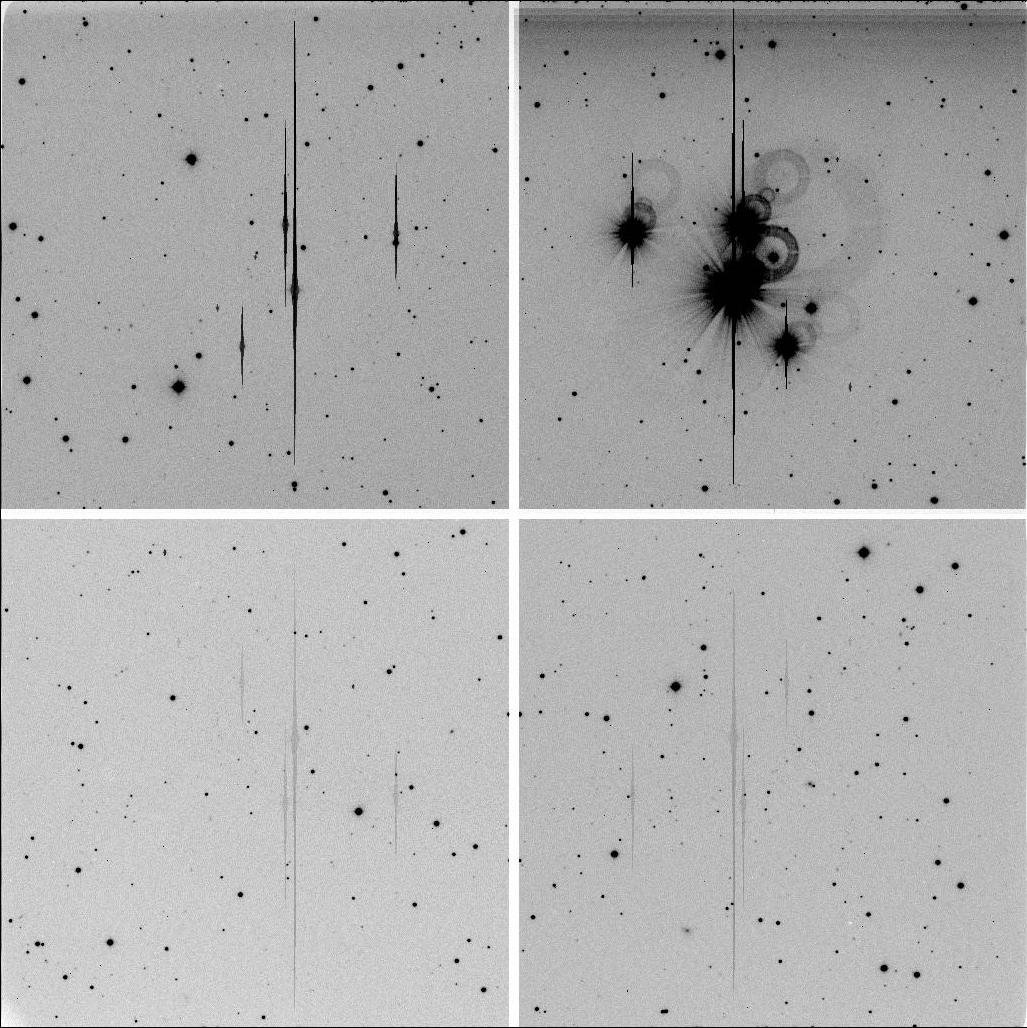
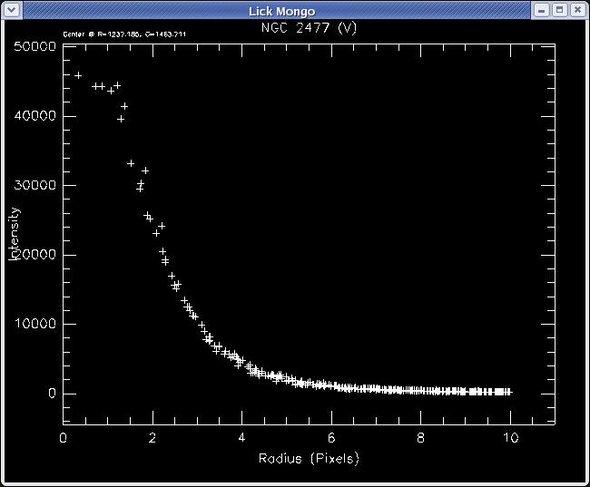
Examination of overexposed star images (saturated but not pushed past full-well and "bleeding") on raw images shows that the nominal full-well saturation occurs at about 50000ADU, or about 44000ADU above bias, corresponding to about 66,000 electrons full-well depth for a nominal gain of 1.4 e-/ADU.

Bias-subtracted radial profile of a saturated star. The sky level in this image is about 55 ADU.

This full-well seems shallow for a 15-micron pixel device, but that's what we measure. Non-linearity seems to start to become an issue 40,000 ADU above bias, and we strongly recommend that you keep important photometric targets below 40K ADU per pixel. For reference, digitization saturates at 65535 ADU, well above the full-well threshold, so operating the camera at a higher than usual bias level (~3500ADU) has no impact on the dynamic range of the camera system.

Detector Cosmetics
The cosmetics of the CCD are excellent, with only three blocked columns (2 adjacent columns in quadrant 4 and one in quadrant 2) and minor cosmetic defects (isolated spots and smears) that appear to flat field out using dome flats.  A bad pixel mask can be used to interpolate across the bad columns (binning 1x1 and 2x2 - simply rename files to exclude '.txt').  The detector is flat to <2% at all wavelengths before flat fielding. Flat fields show a number of out-of-focus dust specks ("donuts") that appear to flat field out in high S/N-ratio dome flats.

Shutter Shading Corrections
The large detector and large, relatively slow shutter means that the shutter shading correction is non-trivial for short exposures. For >10sec integrations, the correction is everywhere <0.3%, but we recommend that flat fields be taken with minimum exposure times of 30sec. For short integrations, a shading correction will be required. The shortest practical exposure time is 0.3sec, for which the shading correction is ~20% from center to edge, with a complex six-sided pattern that reflects the 6-bladed shutter architecture.

Tests during February 2007 show that the shading correction function has been stable on a few-year timescale. We recommend that a set of shading correction data be taken only once per semester and stored on the data-taking computer at the 1-meter as well as in the Yale respository.

Fringing
There is noticeable fringing in the I-band images in bright-sky conditions, and a slight bit of fringing in the R-band. This seems to come out OK in flat fielding and fringing is not expected to be a problem for most applications.

Cross-Talk
When stars are strongly saturated on one quadrant, there is significant crosstalk into pixels in adjacent quadrants. The effect is strongest in side-by-side quadrants, and weaker in top-to-bottom quadrants, consistent with the expected crosstalk signal pathway through the device.
 
Y4KCam Cross-Talk
 
A particularly nice example of cross-talk is shown above, using purposely badly saturated stars on one quadrant. Click on the image to view a higher resolution version (185k JPEG).

Data were taken during February 2011 to calculate correction coefficients.  Those coefficients and brief instructions on the correction methodology can be found here.

Dark Current
The Y4KCam CCD is cryogenically cooled and operated at a temperature of -95 to -100°C. Laboratory measurements found negligible dark current of ~21 electrons/pixel/hour at this temperature, so "dark" images are not required for this CCD.

Pixel Scale
The pixel scale given above is for the BVRI bands, and was measured by fitting to about 150 USNO catalog stars found in the images of SA114. The effective linear pixel scale was consistently 0.289 arcsec/pixel in all bands, so the pixel scale is independent of wavelength for these filters to first order.


Data Acquisition Procedures

Please refer to the Prospero Observer's Guide for the Y4KCam for a complete discussion of data acquisition procedures.  For previous users of Y4KCam, this Quick Guide may be helpful as a refresher.


Data Reduction Procedures

There is a nice package of IRAF-based scripts written by Phil Massey for the Y4KCam that can be found at his website.  In addition, IRAF's QUADPROC can also be used if a keyword file is added to the header.  This file (binning 1x1 or 2x2) can be added to the fits headers using IRAF script noao.artdata.mkheader.  Please note that, to do standardized photometry with Y4KCam, it is necessary to take sky flats to get the full FOV sufficiently flat (see Phil Massey's note on the subject).